World of Level Design™
Tutorials to Becoming the Best Level Designer and Game Environment Artist (since 2008)
MASSIVE 29-Step Quick Start Guide to Creating Custom Static Meshes for Unreal Engine 4
Category: UE4
September 18, 2017

There will come a time where you no longer want to use default Static Meshes or Static Meshes created by someone else to construct game environments. Instead you want to begin creating and using your own custom Static Meshes.
You will quickly discover the amount of work and knowledge you'll need to acquire before creating your own 3d assets.
Custom Static Mesh creation is an involved process that uses multiple software and specific guidelines to follow for each step of the pipeline.
The process itself is actually very straight forward and simple once you've gone through it a couple of times. The problem is getting there. You must know the process sequence, rules, guidelines, options to check and problems to anticipate along the way.
Learning what to do for each step of the pipeline is what takes so much time. You will need to make sure your 3d modeling software is set up correctly for matching the scale and grid spacing in UE4. You will need to model a low-poly and a high-poly mesh, UV for textures and for lightmaps, set hard/soft edges, bake normal maps, create textures, material, collisions, export/import using specific settings while problem-solving at every step of the way.
In this essential quick-start tutorial guide, we'll cover the entire overview from idea to final static mesh and all the steps that have to happen along the way.
I will be using 4 different terms to describe a 3d object: model = object = mesh = static mesh. All mean the same thing - 3d model.
Following MASSIVE Quick-Start Guide Tutorial Includes:
- BSP vs Static Meshes: "Why do I need to use Static Meshes when I have BSP? Couldn't I just use BSP instead of Static Meshes?"
- Software You Will Need
- Preproduction/Planning
- Setting Up Projects
- Setting Up Maya LT/Maya and UE4 for Custom Static Mesh Work
- Set Up Grid in Maya LT/Maya For Unreal Engine 4
- Character Reference Scale in Maya LT/Maya and UE4
- Setting Up a Test Scene in UE4
- Importance of Static Mesh Pivot Points
- Creating Low-Poly and High-Poly Mesh
- Optimizing Low-Poly
- UV Low-Poly for Texturing and Baking
- Setting Hard And Soft Edges (Smoothing Groups)
- Baking Normal Maps and Ambient Occlusion
- What are Lightmaps and How to Create Lightmaps in Maya LT/Maya and UE4
- Creating Collisions in UE4 and Custom Collisions in Maya LT/Maya
- Exporting Options for Static Meshes from Maya LT/Maya
- Importing Options for Static Meshes into Unreal Engine 4
- Setting Up a Working Texture Document
- Creating Albedo/Diffuse Texture
- Creating Detail Normal Maps
- Creating Roughness Texture
- Creating Metallic Texture
- Creating Initial UE4 Material
- Testing Static Meshes
- And much more...
How to Create Game Environment Assets for UE4 in 6 Easy Hours...
If you think this 7,800+ word tutorial doesn't give you enough of the how-to, then you should see the complete, 6+ hours, step-by-step tutorial series on how to create, export and import custom Static Meshes. Click here for "UE4 Custom Static Mesh Formula".
Step 1: What is a Static Mesh?
Static Mesh is a 3d model created in 3d modeling software, exported and imported into Unreal Engine 4. These Static Meshes are either created by you or by someone else and it is what you'll use to construct game environments.
Here are "The Corridor" Static Meshes used to construct the final environment:

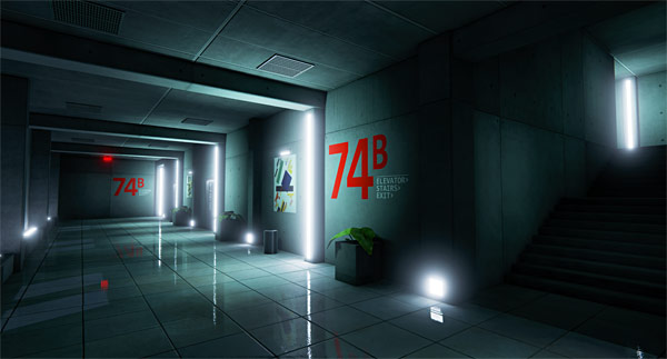
There are 2 types of Static Meshes:
- Static: can't be changed in-game, allows baked lighting and are the fastest to render
- Stationary: primarily used for light actors and not for Static Meshes (source)
- Movable: can be moved and changed in-game, completely dynamic, casts dynamic shadows, slowest to render
Once you place a Static Mesh into your map, you'll be able to set "Static" or "Movable" inside the "Details" panel:

Meshes set to "Static" are non-dynamic objects that will not be interacted or moved during gameplay. These meshes use baked lighting (lightmaps), cheap to render and are perfect for most of architectural geometry in the level. Meshes set to "Static" mobility are what you'll use most of the time.
Meshes set to "Movable" are dynamic objects that can be moved and interacted with during gameplay. These meshes can be used in Blueprints, do not cast pre-calculated/baked shadows (no lightmaps), receive dynamic lights and cast dynamic shadows. You should set meshes to "Movable" on case-by-case basis; otherwise "Static" mobility should be used.
Step 2: BSP vs Static Meshes
"Why do I need to use Static Meshes when I have BSP? Couldn't I just use BSP instead of Static Meshes?"
This question comes up a lot and the answer is no.
It is not whether you should use one or the other but at which step of the pipeline should you use BSP brushes and at which, Static Meshes.
Static Meshes are optimized for UE4 and are cheaper to render than BSP brushes. Also, you will never be able to get the detail required using BSP brushes than you can with Static Meshes.
BSP brushes should be used early in the level design and game environment process to block-in the layout and prototype gameplay mechanics. During this early development stage you don't want to create or use Static Meshes. You must keep focused on scale, spatial relationships, layout, flow, scripting gameplay mechanics and play-testing your level. Since a lot of your design and layout will change, you need to maintain flexibility and BSP brushes allow for quick iteration and change.
As you begin to lock down level's layout and gameplay, begin to replace BSP brushes with Static Meshes. BSP becomes a template for placing Static Meshes.
BSP brush block-in of "The Corridor" environment:

BSP brushes were never meant to be used as final geometry. Most, if not all BSP brushes should be replaced with Static Meshes prior to shipping/releasing your level.
It doesn't mean you can't have any BSP in your finished levels. It is completely acceptable to have BSP brushes as part of your final environment. I often advise to stick to 70/30, 80/20, 90/10 or 100% ratios of Static Mesh to BSP. And if you are going to use some BSP brushes in the final map, then keep them down to a minimum and simple for geometry like as walls, floors, ceiling, columns etc.
Final "The Corridor" environment with 100% custom Static Meshes:

Step 3: Software You Will Need
Software you'll need to create custom Static Meshes range from modeling, sculpting, texturing and baking.
Let's break each one down.
3D Modeling Software
You'll need to model your low-poly mesh that will be used inside Unreal Engine 4 as the final, game-ready asset.

You will need one of the following: Maya LT/Maya, 3ds Max, Blender or Modo. There are other additional modeling software available, but these tend to be the most used, with Maya LT/Maya and 3ds Max being the standard.
Sculpting Software
Sculpting software is used to create high-poly meshes. High-poly objects are used to bake detail down to low-poly object generating a normal map texture. Sculpting software is not a requirement but it doesn't help creating very high-poly detailed meshes.

Sculpting software includes ZBrush or Mudbox. Some modeling software such as Blender and Maya LT/Maya offer some sculpting tools. But if you are going to sculpt high-poly meshes, you should invest in ZBrush or Mudbox.
You can also use modeling software for high-poly work with Sub-D modeling method, which is often used for hard-surface models.
You do need 3d modeling software before trying to use sculpting software. As a beginner, stick with 3d modeling software first, become proficient with that and then get sculpting software.
Texturing Software
Once you created your low-poly, game ready asset, you'll need to texture it. Majority of texture creation and photo editing will be done using Photoshop or Gimp (free alternative), with Photoshop being the standard. You will need to create base color maps, albedo/diffuse maps, detail normal maps, masks, add additional detail, combine images etc.

Some additional software that is often used to generate texture maps includes Substance Designer/Painter and Quixel Suite.
Baking Software
Baking software is used to bake different variety of texture maps such as normal maps, ambient occlusion maps, and base color maps.
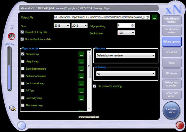
You can use your modeling software (Maya LT/Maya, 3dsMax, Modo, Blender etc.) to bake texture maps or use external software/plug-ins such xNormals, Substance or Handplane. Some software produces better texture bake results than others. I use Maya LT and xNormals.
Unreal Engine 4
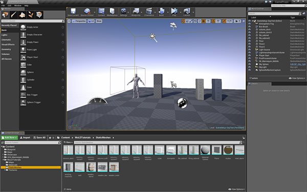
Of course you will need Unreal Engine 4 game engine to import Static Meshes into and use them to construct game environments. UE4 is free to download and use. See this tutorial for "How to Download Unreal Engine 4".
Step 4: Preproduction/Planning
Planning and preproduction is one of the most important steps to starting your project on the right path. It is where you figure out what you are going to create, why you need to create it, how it is going to look, how you are going to do it and how you'll use your time.
Some steps include collecting photo reference, research and reference:

See these two tutorials for more in-depth breakdown on preproduction and planning:
- How to Plan Level Designs and Game Environments in 11 Steps
- Why I Failed for Years at Level Design and Game Environments
Step 5: Setting Up Projects
Before modeling Static Meshes you have to set up proper project folders for your 3d modeling software, Unreal Engine 4 and any additional files that will be created for the project. This helps to keep all the files organized and in one place.
Decide on the project name. In this tutorial I will use "WoLDTutorials". Create new folder and name it:
![]()
Avoid using spaces in the name and if you need to separate for readability, use dashes. Inside "WoLDTutorials" folder, I create additional sub-folders. These are:
- MayaLT or Maya: will contain Maya LT/Maya project related files
- UE4: will contain UE4 related files such as maps, materials and all imported assets (Static Meshes, textures)
- Textures: will contain work-in-progress texture files (.PSD), Quixel files and final textures
- Reference: will contain image reference, concept art, sketches, concept art
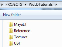
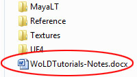
Create any other additional folder you need. I also create a "WoLDTutorials-Notes" text document which will contain to do lists, bugs, fixes, changes and various notes on the project:
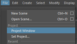
In Maya LT/Maya:
For new project go to "File > Project Window":
Give project a name and click on "New":

Define "Location", a directory where this project folder will be stored in. Navigate to "Projects/WoLDTutorials" folder and into "MayaLT" or "Maya" folder:

"Primary Project Locations" are folders that Maya LT/Maya creates inside the project folder to keep all your files organized. If you know which folders you do not need, you can remove the name and that folder will not be created. I keep "Primary Project Locations" names as default and click "Accept":

Maya LT/Maya creates a project folder with all required sub-folders.
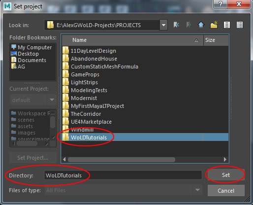
If you need to set Maya LT/Maya to an existing project, go to "File > Set Project":

Choose project folder and click "Set":
In UE4:
Launch "UE4 Launcher", go to "Library" and use drop-down menu to choose which engine version to launch then click "Launch":
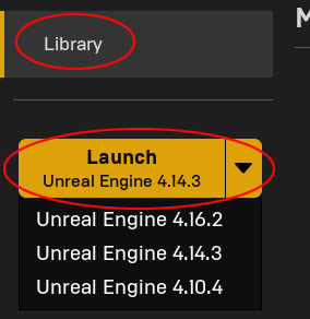
You can also click on UE4 version icons at the top:

Unreal Project Browser will open; switch to "New Project" tab:
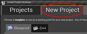
Set the following:
- Choose "Blueprint" or "C++" (Blueprint)
- Choose a "Template" (First Person)
- Choose "Hardware Target" (Desktop/Console)
- Choose "Graphical Level" (Maximum Quality)
- Choose "Additional Content" (No Starter Content)
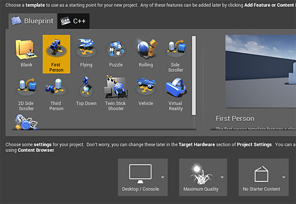
Set "Folder" location for your project to be stored in. This should be inside the project folder. For me it is in "WoLDTutorials/UE4/" folder. Name the project and click "Create Project":

Unreal Engine 4 project folder is now created and all UE4 files will be stored here such as maps, imported assets (Static Meshes, textures, animations), materials, particles, Blueprints etc.
If you need to open an existing UE4 project, go to "Library" and open you project from "My Projects" section:

Textures Folder
Inside "Textures" folder I create additional sub-folders:
- FinalTextures: will contain final .tga texture files
- PSD: will contain work-in-progress Photoshop files
- Quixel: Quixel Suite related files and projects
- SourceTextures: source textures that you've downloaded, such as textures.com

Create any other additional folders you need.
Reference Folder
Inside "Reference" folder, I create additional sub-folders:
- ConceptArt: will contain concept art (inspiration and art direction for the project)
- PhotoReference: will contain collected image reference of the game environment or prop to be created

Create any other additional folders you need.
Step 6: Setting Up Maya LT/Maya for Custom Static Mesh Work
Maximize the interface in 3d modeling software by removing UI elements and menus that aren't going to be used for Static Mesh work.
In Maya LT/Maya go to "Window > UI Elements" and disable:
- Time Slider
- Range Slider
- Command Line (optional)
- Help Line (optional)
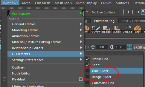
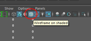
Now enable the following to help with modeling. "Wireframe on Shaded" in Perspective Viewport:
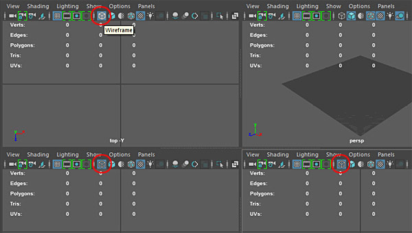
"Wireframe" (Shortcut: 4) in all Orthographic views:
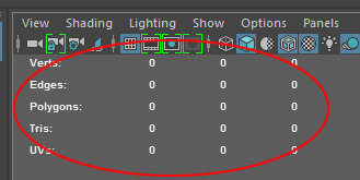
"Display > Heads Up Display > Poly Count" if it isn't showing up already:

Step 7: Setting Up Unreal Engine 4 for Static Mesh Work
Now let's set up UE4 for custom Static Mesh work. In Content Browser (under "Add New" icon) expand "Show/Hide Source Panel". This make it easier to see "Content" folder structure directory:

In Perspective Viewport disable "Real Time" to speed up UE4 and free up some RAM usage:

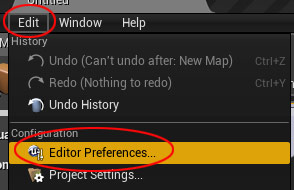
I like to manually save my work so I disable auto-save, "Edit > Editor Preferences: Loading & Saving" and disable "Auto-Save":

Of course leave this on if you prefer "Auto-Save" feature.
In Content Browser create folders to import your assets into. This will help to keep your content inside UE4 organized. Right-click inside Content Browser, on "Content" folder and choose "New Folder":
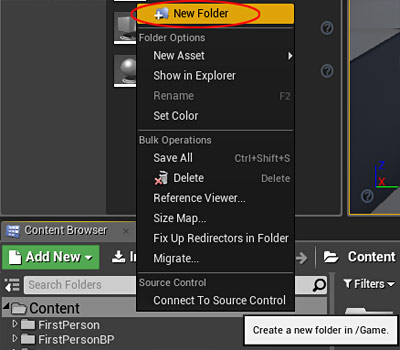
Create the following folders:
- Maps
- StaticMeshes
- Textures
- Materials
- Blueprint

Create any other additional folders you need.
If these folders are empty and you close Unreal Engine 4, they will be automatically deleted. In order for a folder to be saved, you must import or create an asset inside that folder.
Personally, I create one main folder and then all other folders "Maps, StaticMeshes, Textures, Materials, Blueprint" are created within this main folder:

Step 8: Set Up Grid in Maya LT/Maya For Unreal Engine 4
Set up your 3d modeling software grid spacing to match Unreal Engine 4. It will keep your Static Meshes on the grid and maintain 1=1 scale ratio.
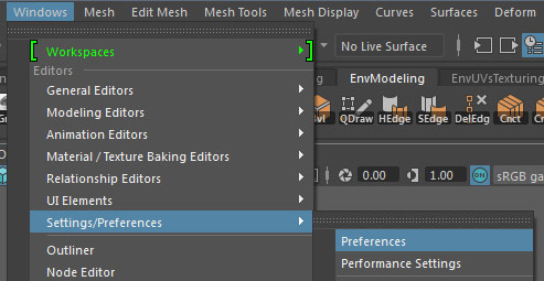
Go to "Window > Setting/Preferences > Preferences":
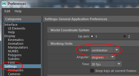
Under "Settings: Working Units > Linear: Centimeter":
Go to "Display > Grid Option":

Under "Size" set the following values to match Maya LT/Maya grid to UE4:
- Length/Width: 1,000 units (size of the gird in perspective viewport; overall grid size and not the size of each grid unit)
- Grid lines every: 10 units (grid unit spacing; this value corresponds to changing the grid size in UE4; use 5, 10, 50, 100 values to match UE4 grid spacing)
- Subdivisions: 1 (set this value to 1 to match UE4)

Step 9: Character Reference Scale in Maya LT/Maya
Create or insert a character reference to help you judge size and proportion of game environments. This can be a 3d character model or a simple cube with dimensions of character in-game.
Important Measurements to Remember:
- 1 Centimeter = 1 Unreal Unit
Default Character Scale/Size in UE4:
- Height: 180 units
- Width/Depth: 40-60 units
Maya LT/Maya Scene and Character Reference Set Up:
I need a character size reference in the scene to judge proportion and scale. In Maya LT/Maya we'll use a cube. Start a new scene "File > New Scene":

Default character scale/size in UE4 is:
- Height: 180 units
- Width/Depth: 40-60 units
Create a cube with the following dimensions:
- Width: 60
- Depth: 60
- Height: 180
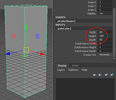
Adjust these values to fit your project and your own in-game character (if you have one).
Modify the pivot point and align the cube to the grid:
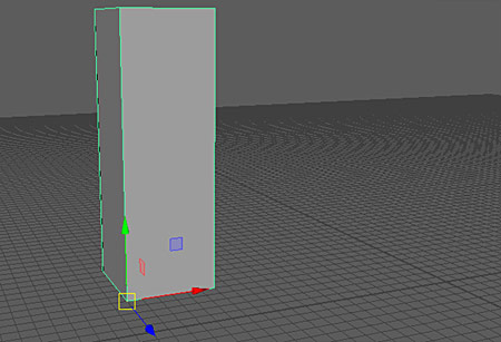
Name the cube "Scale":
![]()
Place it into a Display layer and lock it to "R" so it is un-selectable:
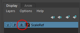
Save the scene "File > Save Scene As" and name it "ScaleTemplate" or anything else you want:

The Maya LT/Maya file will be saved inside "/scenes" folder:

Step 10: Setting Up a Test Scene in UE4
You can use already created level, new level or Static Mesh Editor to test your imported Static Meshes.
I usually test new imported Static Meshes in a default scene I've set up. Let's create it now.
Go to "File > New Level":

And choose "Default":

Default levels come with a ground plane, sky, light, atmospheric fog and player start:

I need to add some additional actors and adjust various settings. These actors are "Sky Light", "Post Process Volume", "Spherical Reflection Capture", "Player Start" and "Lightmass Importance Volume":
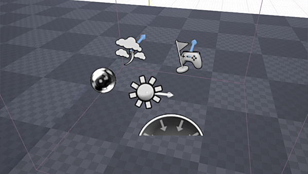
Select the "Sky Sphere":

Adjust "Sky Sphere" properties. I want to have a solid sky background without clouds so it doesn't distract from viewing Static Meshes. Select "Sky Sphere" and in "Details" panel set "Cloud Opacity" to "0" to remove the clouds:

"Sky Light" will automatically work because the scene already has a "Sky Sphere". "Sky Light" will brighten indirectly lit areas (areas in shadows):

Insert "Post Process Volume":


Adjust "Post Process Volume" settings in the "Details" panel:
- Enable "Unbound"
- Set "Auto-Exposure: Min/Max Brightness: 1.0"
- Enable "Crush Highlights: 1.0"
- "Ambient Occlusion: Quality: 100"
- "Screen Space Reflections: Quality: 100"
Insert "Spherical Reflection Capture" to calculate reflections correctly:

Insert "Lightmass Importance Volume":

Adjust the size of "Lightmass Importance Volume" to surround your test area:

Set Anti-Aliasing to FXAA, go to "Edit > Project Settings":

"Rendering: Anti-Aliasing Method: FXAA":

Save this level into your "Maps" folders with any name you want. We'll use this scene to insert and test Static Meshes. Go to "File > Save Current As":
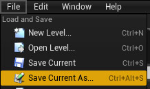
Step 11: UE4 Character Reference Set Up
In UE4, you have two options for character reference scale, BSP brush or UE4 Mannequin.
For BSP Brush:
Go to "Geometry" tab and create "Box" BSP brush with following dimensions and align it to the ground plane:
- Width: 60
- Depth: 60
- Height: 180


For "UE4 Mannequin":
Go to "Library", scroll to the bottom and find "UE4 Mannequin: Mobile". Click "Add To Project":

Choose which Project you want to add "UE4 Mannequin" to and click "Add to Project":

In UE4, insert "UE4 Mannequin: Mobile" into the scene from the Content Browser: "UE4_Mannequin_Mobile/Mesh/SK_Mannequin_Mobile":


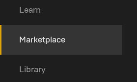
If you don't have "UE4 Mannequin: Mobile" then you'll need to download from UE4 Marketplace (free). Go to "Marketplace":
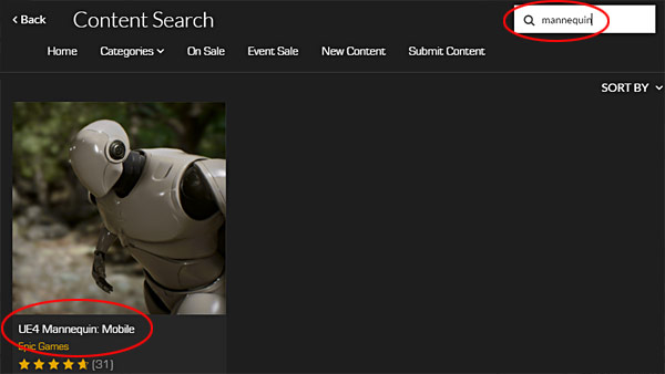
Search for "UE4 Mannequin":
Click on "Free":

Then in "Library" section, scroll to the bottom and "Add to Project":

Step 12: Importance of Static Mesh Pivot Points
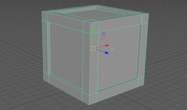
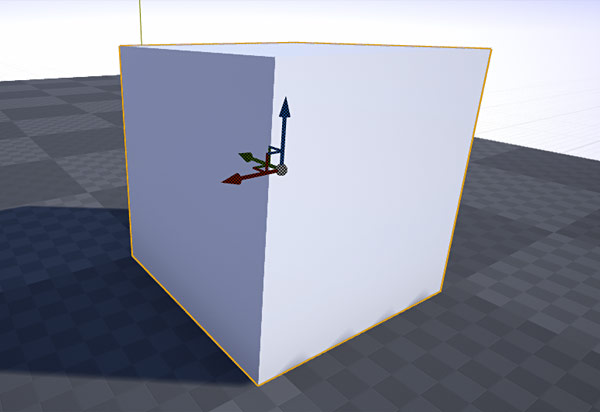
When you select an object in 3d modeling software or Unreal Engine 4 you will see the move/scale/rotate gizmo appear. The location of this gizmo is object's pivot point. Pivot point is where the 3d model will move/scale/rotate from.
In Maya LT/Maya:
In Unreal Engine 4:
You want to control where this pivot point is on Static Meshes.
Important: All pivot points in 3d modeling software are automatically positioned at (0, 0, 0) world space on export:
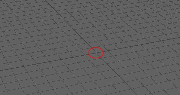
No matter where the 3d model is positioned in the world, pivot point will be reset to (0, 0, 0) world origin on export. Example below is an object off to the side (away from world origin). The pivot point on this mesh is currently located at a bottom vertex:

When exported and imported into UE4, the pivot point will be reset to (0, 0, 0) while the object is still off to the side:
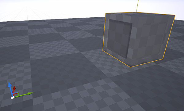
First, place pivot point on the Static Mesh where you want it. In Maya LT/Maya use "Insert" key or press and hold "D" key to modify the pivot point. The gizmo will change to this, meaning you are modifying the pivot point:
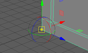
I position the pivot point on this crate at bottom vertex corner:

Hold "X", "C", "V" keys to snap the pivot point to gird, edge or vertex:
- X = snap to grid
- C = snap to edge
- V = snap to vertex
Same shortcut keys will also snap the object itself to grid, edge or vertex.
Second, position the object with new pivot point at (0, 0, 0). Make sure the pivot point is at the world origin:

Freeze Transformations on the object. This helps to bring back the model to world origin using Channel Box input value for Translate and Rotate back to 0 for quick re-exporting. Go to "Modify > Freeze Transformations":

Step 13: Creating Low-Poly and High-Poly Mesh
It is now time to begin creating your Static Mesh. Use your 3d modeling software (Maya LT/Maya, 3dsMax, Blender, Modo etc.) and model your object.
There are 2 primary modeling methods you'll be using.
Method #1: create low-poly first (left), then high-poly (right) second:

Method #2: create high-poly first (left), then low-poly (right) second:
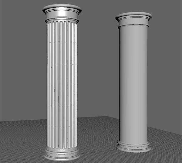
- Low-poly mesh is the game-ready object that will be used in Unreal Engine
- High-poly mesh is used to bake normal map textures from
For high-poly object you could use sub-d modeling or sculpt it in ZBrush/Mudbox. Method used will greatly depend on the type of object you are creating and your experience.
Start here to learn how to use Maya LT/Maya for game environment art to model your own game environment assets/props.
Step 14: Optimizing Low-Poly
Optimizing low-poly, game-ready Static Mesh involves lowering polygon/triangle count by removing unnecessary edges, faces, vertices, checking/fixing model for errors such as non-manifold geometry, lamina faces, concave faces, faces with holes, ngons, non-planar faces, reversed normals, overlapping geometry etc.
You can run Cleanup command in Maya LT/Maya, "Mesh > Cleanup" to find geometry problems to fix:
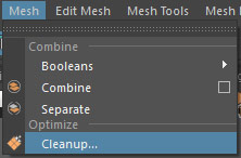

You also want to constantly export and import the Static Mesh into UE4 to catch any problems early.
Step 15: UV Low-Poly for Texturing and Baking
You have to unwrap low-poly mesh for texturing and prior to baking any maps such as Normal and Ambient Occlusion maps:
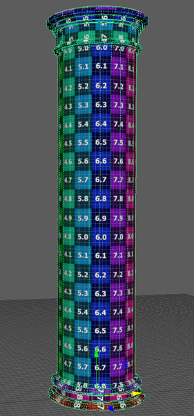
High-poly mesh does not need to be UVed (unless painting textures with sculpting software).
UVing your assets/props can be very frustrating and tedious but it doesn't have to be. Third module in "3D Game Environment Modeling/UVing Foundation with Maya LT™/Maya®" covers how to UV unwrap your meshes.
Step 16: Setting Hard And Soft Edges (Smoothing Groups)
Define hard/soft edges on your low-poly model. Hard/soft edges are also known as smoothing groups.
Soft edges will yield smooth transition between edges:

Hard edges will yield sharp transition between edges:

Hard and Soft edges set in Maya LT/Maya or any other 3d application will directly translate to UE4:

Select the object, hold "Shift + Right Mouse Click > Soften/Harden Edge > Toggle Soft Edge Display":

- Solid Line = Hard Edge
- Dashed Line = Soft Edge
Go through the model and set hard or soft edges. Switch to edge component mode. Select one or more edges which you want to harden or soften, then Hold "Shift + Right Mouse Click > Soften/Harden Edge" and choose "Soften Edge" or "Harden Edge":

You can also set "Hard" or "Soft" edges on the entire object at once. Select the model, Hold "Shift + Right Mouse Click > Soften/Harden Edge" and choose "Soften Edge" or "Harden Edge". But most of the time you'll be doing this to specific edges.
Step 17: Baking Normal Maps in Maya LT
Normal map is a 2d texture that contains baked information from high-poly mesh or from converted 2d texture, when this normal map is applied to a low-poly mesh in-game it simulates high-resolution detail without adding additional polygon count. Your low-poly, in-game model look high-poly due to a 2d normal map texture but in reality it is just a low-poly mesh.
Here is an example of low-poly without (left) and with (right) a normal map:

Baking normal maps can be done inside 3d modeling software (Maya LT/Maya, 3dsMax, Modo, Blender etc) or external software/plug-in (Handplane, Substance Baker, xNormals).
You can generate normal maps using high-poly to a low-poly bake:

Or convert a 2d image to a normal map:

Usually, you'll use both. High-poly to low-poly bake is used to generate overall form and shape of the model. Converting 2d image to a normal map is used to create normal map detail such as bumps, scratches and dents. Both normal maps are then combined into one.
But normally when you hear "baking" normal maps, this involves using high-poly and low-poly object and this is what we'll focus on in this section. We'll deal with detail normal map later.
We'll use "Turtle Baker" in Maya LT, which produces good results.
Guidelines for Baking:
Few guidelines must be followed to achieve good baking results.
- You must place high-poly to overlap low-poly
- Your high-poly must match the shape of low-poly and vice versa
- Low-poly must contain unwrapped UVs and these UVs must be inside (0,1) space
- Overlapping UVs must be moved outside (0,1) space, temporarily; overlapping UVs cause problems during the bake
- If your object is made up of multiple, overlapping pieces you may need to move/separate those pieces and bake them separately (this is also known as: exploding your model)
- Export low-poly and high-poly objects as FBX if baking in another software such as xNormals or bake right inside 3d modeling software, in our case it will be Maya LT/Maya using Turtle Baker
Step 1 for Baking Normal Maps in Maya LT/Maya: Set up Baking Layers
Go to "Windows > Material/Texture Baking Editors > Turtle > Bake Layer Editor":

Click on "New Layer" and "Edit Layer" to rename:

Add low-poly under "Target Surfaces" and high-poly under "Source Surfaces":
- Target Surface: Low-Poly object
- Source Surfaces: High-Poly object

Step 2 for Baking Normal Maps in Maya LT/Maya: Texture Baking Settings
Go to "Windows > Material/Texture Baking Editors > Texture Baking Settings":
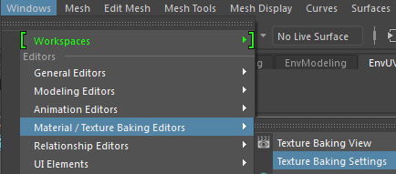
Enable Bake and under "Sampling Tab: Anti-Aliasing" adjust "Min Sample Rate: 1" and "Max Sample Rate: 2". Change "Max Sample Rate" to "4" when doing a final bake:

Switch to "Baking Tab":

Choose which layer you want to bake and set "Bake To: Texture". "Target Surfaces" and" "Source Surfaces" will be set from "Bake Layer Editor" and "Envelope" will be empty":

Transfer Settings:
- Sampling Preset: Closest
- Front Range: 100
- Back Range: 100
- Front Bias: 0
- Back Bias: 0
- Transfer Space: World Space
- Selection Mode: Distance
- Mismatch Mode: Use Background
- Ignore Inconsistent Normals: enabled

Texture Bake Settings:
- Height/Width: pick texture size using power of 2 value (i.e. 32, 64, 128, 256, etc.)
- Save to File: enabled
- File Format: TGA
- Bilinear Filter: enabled
- Edge Dilation: 5 (edge padding)
- UV Range: Default (0,1)

Under "Outputs: Shader Outputs" switch to "Normal Map" and disable everything else:

Under "Advanced Settings: Normal Map" set "Coordinate System" to "Tangent Space":

Step 3 for Baking Normal Maps in Maya LT/Maya: Baking
Go to "Windows > Material/Texture Baking Editors > Texture Baking View":
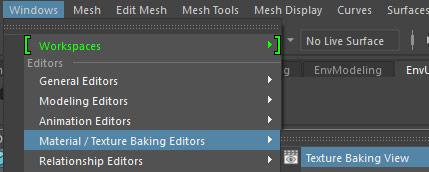
Click on "Bake (Turtle)" icon:

Normal Map will now be baked:
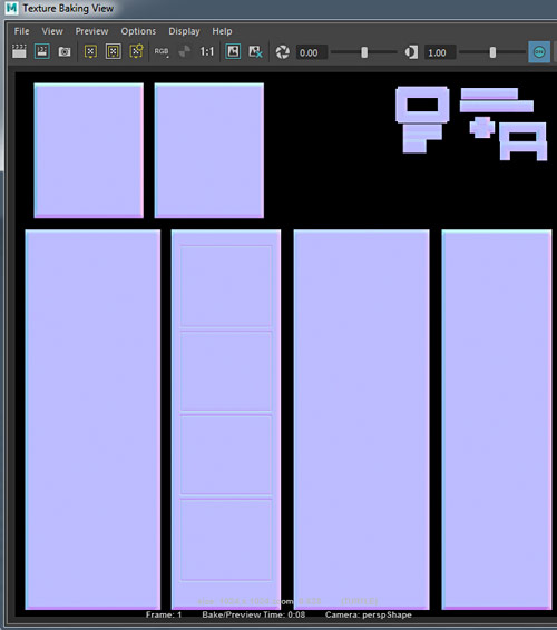
After you are done with the bake, move overlapping UVs back into (0, 1) space, if you happened to move them out. Also, if you had to bake multiple pieces separately then you'll have to combine all normal maps together in Photoshop.
You'll find all baked normal maps inside Maya LT/Maya project folder, "\turtle\bakedTextures":
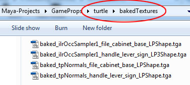
Step 18: Baking Ambient Occlusion in Maya LT
You may also want to bake an Ambient Occlusion map. Ambient Occlusion is a grayscale image that define shadows in crevices of your model. Prior to UE4, you would overlay AO map on top of your Diffuse texture. Now UE4 material editor has its own Ambient Occlusion input:

You don't always need Ambient Occlusion map but it does make a difference. Here is an example without AO (left)and with AO (right):

Guidelines for Baking AO maps:
Baking guidelines are almost identical for AO as they are for normal maps, but let's go through them again:
- You must place high-poly to overlap low-poly
- Your high-poly must match the shape of low-poly and vice versa
- Low-poly must contain unwrapped UVs and these UVs must be inside (0,1) space
- Unlike Normal Maps, if your object is made up of multiple, overlapping pieces you do not need to move/separate those pieces to bake them separately
- Export low-poly and high-poly objects as FBX if baking in another software such as xNormals or bake right inside Maya LT/Maya using Turtle Baker
Step 1 Baking AO Maps in Maya LT/Maya: Set up Baking Layers
You can use the same baking layer as you did for Normal Maps.
If you didn't set them up yet then go to "Windows > Material/Texture Baking Editors > Turtle > Bake Layer Editor":

Click on "New Layer" and "Edit Layer" to rename:

Add low-poly under "Target Surfaces" and high-poly under "Source Surfaces":
- Target Surface: Low Poly object
- Source Surfaces: High Poly object

You may have just a single object to bake or you may have multiple objects. In my example, I have multiple low-poly and high-poly meshes that I will bake at the same time, so I add them all in.
Step 2 Baking AO Maps in Maya LT/Maya: Texture Baking Settings
Go to "Windows > Material/Texture Baking Editors > Texture Baking Settings":

Enable Bake and under "Sampling Tab: Anti-Aliasing" adjust "Min Sample Rate: 1" and "Max Sample Rate: 2". Change "Max Sample Rate" to "4" when doing a final bake:

Switch to "Baking Tab":

Choose which layer you want to bake and set "Bake To: Texture". "Target Surfaces" and" "Source Surfaces" will be set from "Bake Layer Editor" and "Envelope" will be empty":

Transfer Settings:
- Sampling Preset: Closest
- Front Range: 100
- Back Range: 100
- Front Bias: 0
- Back Bias: 0
- Transfer Space: World Space
- Selection Mode: Distance
- Mismatch Mode: Use Background
- Ignore Inconsistent Normals: enabled

Texture Bake Settings:
- Height/Width: pick texture size using power of 2 value (i.e. 32, 64, 128, 256, etc.)
- Save to File: enabled
- File Format: TGA
- Bilinear Filter: enabled
- Edge Dilation: 5 (edge padding)
- UV Range: Default (0,1)

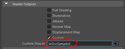
Under" Outputs: Shader Outputs" switch to "Custom Shader" and disable everything else:

Click on arrow icon next to "Custom Shader" input:
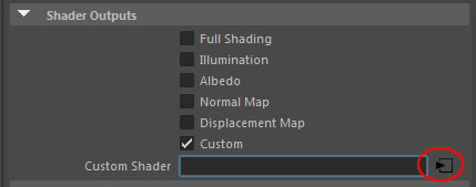
"Create Shading Node" menu will pop up. Select "Surface" and choose "Ilr Occ Sampler":
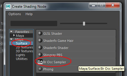
"Custom Shader" input will now have "ilrOccSampler1":
If you go to "Hypershade" and double-click on "ilrOccSampler1" node:
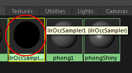
You'll be able to adjust various properties for Ambient Occlusion material inside Attribute Editor, such as "Min/Max Sample Rays":

Step 3 Baking AO Maps in Maya LT/Maya: Baking
Go to "Windows > Material/Texture Baking Editors > Texture Baking View":

Click on "Bake (Turtle)" icon:

Ambient Occlusion map will now be baked:
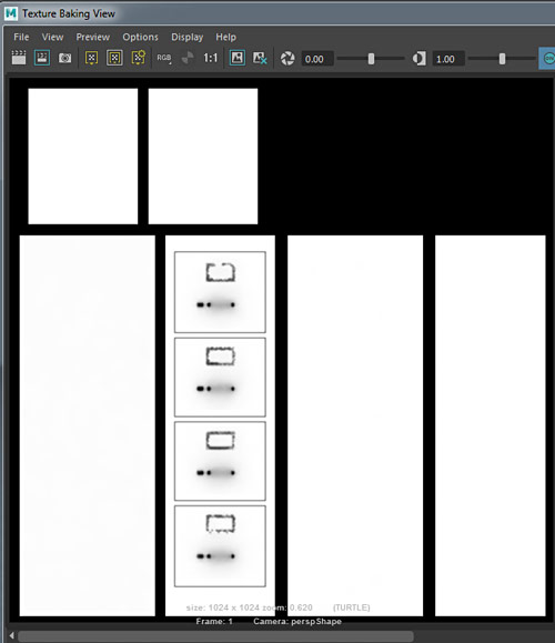
You'll find all baked normal maps inside Maya LT/Maya project folder, "\turtle\bakedTextures":

Step 19: Creating Lightmaps
In order for a Static Mesh to display correct light/shadow information, it must have properly created Lightmaps.
Lightmap is a texture that stores light/shadow information for the Static Mesh after building lights. Second UV channel is used to store this lightmap within your Static Mesh.
Here is a Static Mesh with Lightmaps (left) and without properly created Lightmaps (right):

Remember that Static Meshes with mobility set to "Static" require lightmaps and Static Meshes with mobility set to "Movable" do not. Since most Static Meshes in your level will be set to "Static", you have to spend time creating 2nd UV channel and unwrap it specifically for lightmaps. So Static Meshes will have a texturing UV channel and a Lightmap UV channel.
If a Static Mesh doesn't have a 2nd UV channel, UE4 will use texture UV channel for its lightmap, but there are few problems with this.
Lightmap Guidelines:
- Lightmap must be stored in a separate, 2nd UV channel
- Lightmap UVs have to be unique, meaning they can't overlap
- UV layout should be treated differently than texture UVs
- Lightmap UV resolution will usually be lower than texture resolution
You can create a 2nd UV channel for lightmaps in UE4 or 3d modeling software. Best way will be using modeling software.
Lightmaps in UE4:
Lightmap UVs are can be generated automatically during import using "Generate Lightmap UVs" option:

Or through "Static Mesh Editor" after import:

Using "Static Mesh Editor" will give you more settings to control prior to creating a 2nd UV lightmap channel. Open "Static Mesh Editor" by double-clicking on a Static Mesh from Content Browser. Set the following options under "LOD0: Build Settings" tab:
- Enable "Generate Lightmap UVs"
- Set "Min Lightmap Resolution" (use power of 2 values)
- Set "Source Lightmap Index"; source from which lightmap UVs are generated from (will usually be set to 0, which is object's texture UVs)
- Set "Destination Lightmap Index"; location to store lightmap channel UVs (set this to 1)
Click on "Apply Changes".

Click "UV" icon in the toolbar, use drop down to the right to select "UV Channel 1":

Check Lightmap UVs:

Back in "Details" panel, under "Static Mesh Settings" set default lightmap resolution (use power of 2 values, i.e. 32, 64, 128, 256, etc.) and set "Lightmap Coordinate Index" to 1:
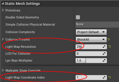
Static Mesh resolution you use will depend on the complexity of the Static Mesh and where in the level it will be used. Higher lightmap resolution will produce better quality lightmaps but with increased texture size.
Click "Save":
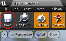
Inside the level, click "Build" to see how lightmaps look on your Static Mesh:

Using "Generate Lightmap UVs" in UE4 will often create light/shadow artifacts. This is due to UE4 using your texturing UVs to generate lightmaps. Since lightmaps UVs have to be treated differently than texture UVs you will have better results if you unwrap the lightmap UVs in 3d modeling software.
Lightmaps in Maya LT/Maya:
Select the object and open "UV Editor". Create new empty UV set or copy existing UVs into new UV set:
- "UV Sets > Create Empty UV Set"
- "UV Sets > Copy UVs to UV Set > Copy into New UV Set"

I usually choose "Copy into New UV Set"; this copies existing texture UVs into a new UV set.
Go to "UV Sets" and choose which UV set you are working with ("map1" or "map2", I renamed mine to "lightmap"):
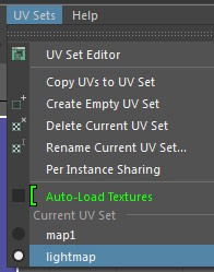
You can rename a UV sets to identify them better, "UV Sets > Rename Current UV Set":
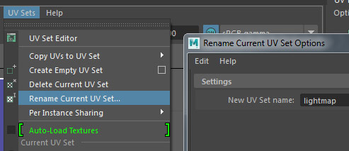
At this point go ahead and unwrap object's UVs for Lightmaps.
Remember, two important rules for lightmapping UVs are:
- Cut/separate UVs along edges where there is a significant change in light/shadow, such as 90 degree angles
- Do not have any overlapping UVs within your lightmap
Apply "Layout" options for better lightmap layout. Go to "Modify > Layout" (options):
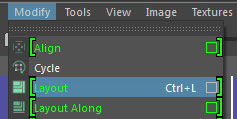
Set the following properties:
- Unfold3D
- Texture Map Size: lightmap resolution size
- Padding Units: Pixels
- Shell Padding and Tile Padding: 2-8 units (lower value for high resolution lightmaps, higher value for low resolution lightmaps)
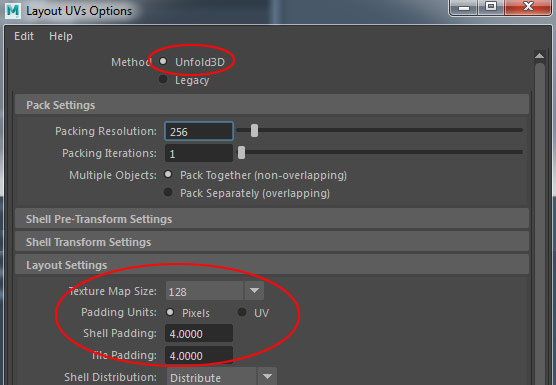
Click "Apply" to see the results:
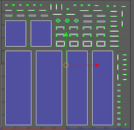
Export/import the Static Mesh into UE4 and "Build" to see how lightmaps look on your Static Mesh.
Step 20: Creating Collisions
Collision simulates physics so the player can't walk through Static Meshes and other objects can collide with them. There are two ways to create collisions:
- Inside UE4's "Static Mesh Editor" (great for simple Static Meshes)
- In 3d modeling software to be exported along with your object (best option for complex Static Meshes)
Collision in UE4:
You can generate collision automatically on import by enabling "Auto Generate Collision":

But you will have more control over collision creation if you use "Static Mesh Editor". Open "Static Mesh Editor" by double-clicking on a Static Mesh from "Content Browser" and enable "Collision" view in Static Mesh Editor's toolbar:
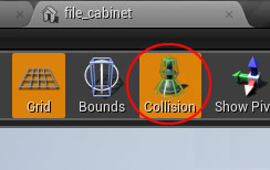
Light green/aqua wireframe will appear on the mesh:
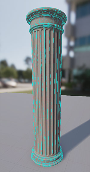
The object doesn't have collisions yet, this is "Per Poly Collision" preview display. "Per Poly Collision" calculates collisions per poly instead of simple hull primitives. Using "Per Poly Collision" increases memory cost and should be used on case-by-case basis. By default "Per Poly Collision" is not enabled but if you do want to use it then under "Static Mesh Settings" tab, set "Collision Complexity" to "Use Complex Collision as Simple":
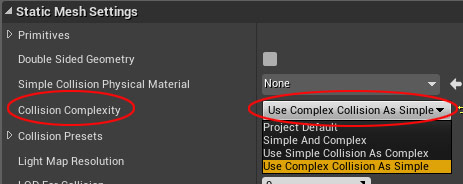
Now, back to custom collisions that are more memory efficient and one you'll want to use most of the time.
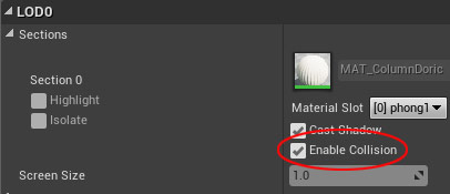
Temporarily disable "Enable Collision" to remove the display preview for "Per Poly Collision". We will turn this back on after we are done:

Go to "Collision > Add" and choose collision type:

Choose different collision options available to see which one works best for your Static Mesh. Here I chose "Add 26DOP Simplified Collision":
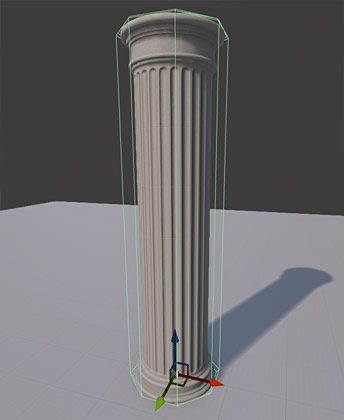
Using "Collision > Add" more than once, will not replace current collision but add to it:

You'll have to remove current collisions if you want to add new or replace existing collision. Select the collision primitive and go to "Collision > Remove Collision" or press "Delete":

Complex meshes will need more complex collisions, for this you can use "Collision > Auto Convex Collision":
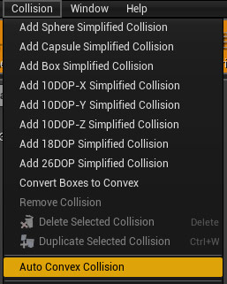
You must have "Enable Collision" checkbox turned on for this to work:
"Convex Decomposition" menu will pop-up on bottom of "Details" panel:
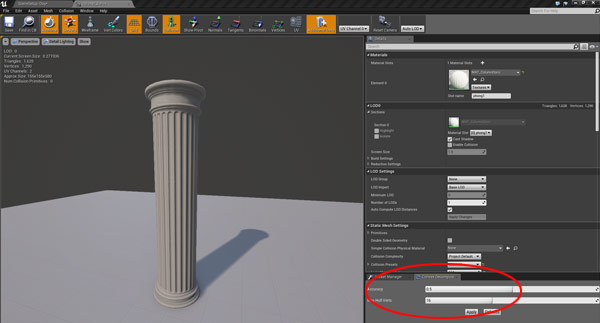
- Set "Accuracy" (lower value generates fewer primitives)
- Set "Max Hull Verts" (increase/decrease number of collision vertices, higher value - more precise collision but more complex the collision hull)

Click "Apply" and take a look at the results:

You can scale, rotate and move each collision hull in the Static Mesh Editor:

- "Left Click" to select a collision primitive and "Ctrl + Left Click" to add to or remove from a selection
- Use "Ctrl + W" to duplicate selected collision primitive
- Press "Spacebar" to cycle between Scale/Rotate/Move
- Press "Delete" to remove selected collision primitive
When done with adding collision, click "Save":

Collision in Maya LT/Maya:
Collision in Maya LT/Maya or other 3d modeling software is a separate geometry primitive with a specific prefix in the name followed by name of the Static Mesh.
For example, name of the mesh below is "dumpster" and name of the collision is "UCX_dumpster". The collision is placed on top of the Static Mesh (I made the material see-through for the collision so you can see it better in the example):
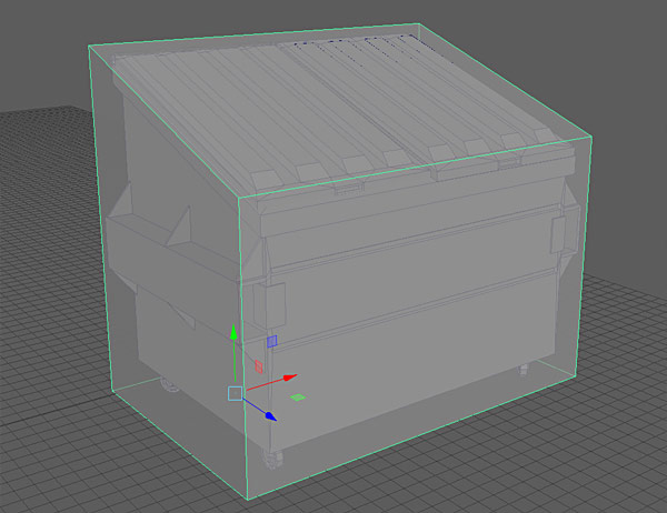
To export, select both the Static Mesh and collision/s, then export normally; on import UE4 will recognize the prefix and use it as collision.
There are various collision prefixes you can use.
Collision Prefix Names:
- UBX_ (box object, do not move vertices or deform the object other than to square or rectangle)
- USP_ (sphere, do not move vertices or deform the object, must be scaled uniformly)
- UCX_ (convex object, vertices can be moved, faces can be extruded, cannot be concave)
- UCP_ (capsule poly mesh collision)
Naming Convention for Collision:
- Single Primitive Collision: Prefix_ObjectName
- Multiple Primitive Collisions: Prefix_ObjectName_00, Prefix_ObjectName_01, Prefix_ObjectName_02 etc.
For example, this pillar Static Mesh had to have 3 collision primitives. Name of the Static Mesh is "column_LP":
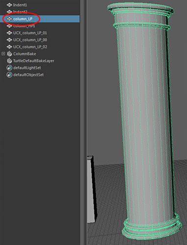
Name of the collision primitives are: UCX_column_LP_00, UCX_column_LP_01, UCX_column_LP_02:
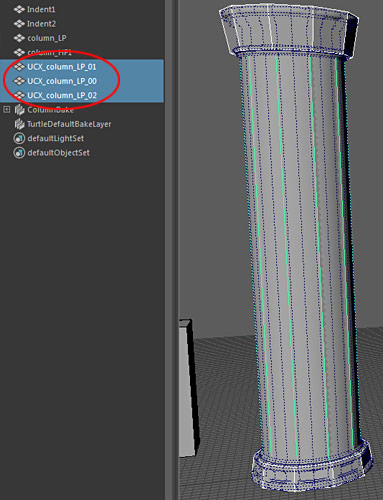
Then all collisions are selected along with the Static Mesh and exported as usual.
For multiple primitive collisions, it is recommended to leave a tiny gap between primitives:

Step 21: Exporting Options for Static Meshes from Maya LT/Maya
There are 2 options you can use to export Static Meshes from Maya LT/Maya for UE4. First option is manually export a selection and second option is using "Send to Unreal".
The option you use doesn't matter, results will be the same. Although in Maya LT, one main advantage of using "Send to Unreal" is unlimited polygon count on export, while manual method has 250,000 polygon limit.
Export Option #1: Manual
Make sure the object's pivot point is positioned at world origin (0, 0, 0):

Select the object and go to "File > Export Selection":

Choose a folder to export into. I created "ExportedMeshes" folder within Maya LT/Maya project directory:

Set "Files of type" to "FBX export" and name the Static Mesh to export:

Set the following options for Static Mesh Export (you'll only have to do this once):
- Enable "Smoothing Groups"
- Enable "Smooth Mesh"
- Enable "Triangulate"
- Units: Automatic
- Axis Conversion: Up Axis: Y
- FBX File Format: Type: Binary
- Version: FBX 2016/2017 (any newer/older versions can be used, as long as you don't experience any "FBX out of date" errors on import)
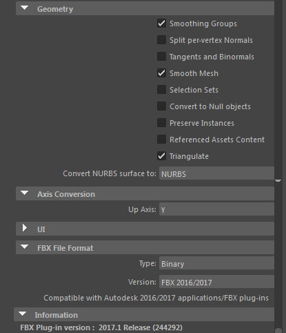
Click on "Export Selection" to export the Static Mesh.
Maya LT/Maya will remember all options set, from now on, select the object and choose "File > Export Selection", name the Static Mesh and hit "Export Selection".
Export Option #2: Send to Unreal
"Send to Unreal" option requires you to set up a valid UE4 project location where all Static Meshes will be exported into. This has to be done once and prior to using "Send to Unreal".
Go to "File > Send to Unreal: Set Unreal Project":
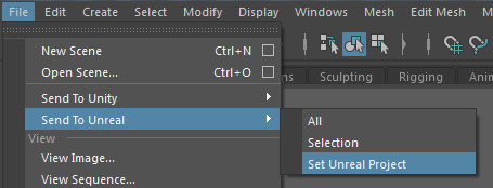
Navigate to a valid Unreal Engine 4 project and select a folder within it where you want to export all current/future meshes into. I created a new folder within an existing UE4 project directory and named it "ExportedMeshes". Name this folder anything you want. Then click "Select":

Make sure the object is positioned at world origin and pivot point at (0, 0, 0):

Select the mesh to export and go to "File > Send to Unreal > Selection" or "All":

Set "Files of type" to "FBX export" and name the Static Mesh to export:

Set the following options for Static Mesh Export (you'll only have to do this once):
- Enable "Smoothing Groups"
- Enable "Smooth Mesh"
- Enable "Triangulate"
- Units: Automatic
- Axis Conversion: Up Axis: Y
- FBX File Format: Type: Binary
- Version: FBX 2016/2017 (any newer/older versions can be used, as long as you don't experience any "FBX out of date" errors on import)

Click on "Export Selection" to export the Static Mesh.
Maya LT/Maya will remember all options set, from now on, select the object and choose "File > Send to Unreal > Selection" or "All", name the Static Mesh and hit "Export Selection".
Step 22: Importing Options for Static Meshes into Unreal Engine 4
After you've exported the Static Mesh from 3d modeling software, it is time to import it into Unreal Engine 4.
In Content browser select the folder to import into. In my case this is "Static Meshes" and click "Import":
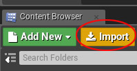
Navigate into a folder where you exported the Static Meshes into, select the object and click Open:

In the "FBX Import Options" (some options will be on case-by-case basis):
- Disable "Auto Generate Collision"
- Enable "Remove Degenerates"
- Disable "Generate Lightmap UVs"
- "Normal Import Method: Import Normals"
- Disable "Import Materials"
- Disable "Import Textures"
- Enable "Override Full Name"
- Enable "Convert Scene"
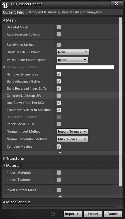
Click "Import".
"File > Save All" to save your scene and imported assets:

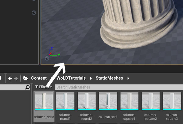
Place Static Mesh from Content Browser into the level by "Left Click Hold and Drag" into perspective viewport:
For "Normal Import Method" there are two other options "Calculate Normals" and "Import Normals and Tangents" in addition to "Import Normals":

These settings are a more advanced and have to do with how you set up object's normals and tangents in 3d modeling software. If you haven't modified normals and tangents on your models, choose "Import Normals". If you don't know what that means, keep it at "Import Normals" until you have more experience editing normals and tangents.
- Calculate Normals: The engine computes normals and tangents. Smoothing group and normal info is discarded from the FBX info
- Import Normals: normals are imported from the FBX file, tangents are computed by the engine
- Import Normals and Tangents: The normals and tangents are imported from the FBX file and nothing is computed by the engine
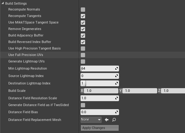
Many options above can be changed after import through Static Mesh Editor. Double-click on the Static Mesh from the Content Browser to open Static Mesh Editor and change settings in "Details" panel under "LOD0: Build Settings":

Step 23: Setting Up a Working Texture Document
Set up a Photoshop document for Static Mesh texture. This file will be your working texture file for a specific Static Mesh and contain all the layers and adjustments for albedo/diffuse, roughness, normal map etc.
In Photoshop:
Go to "File > New" to start a new document:

Set "Width and Height" (use power of 2 values):

Go to "File > Save As" and save the texture document as PSD file:

You want to keep your Photoshop file organized, so inside "Layers" panel, create folders for:
- Normal Map
- Albedo Diffuse
- Roughness
- Any other texture map you'll need for this Static Mesh

In Maya LT/Maya:
We need to save "UV screenshot" layout from Maya LT/Maya to be used in Photoshop so we know what part of the Static Mesh we are texturing.
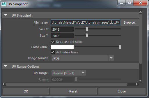
Open up UV Editor and go to "Image > UV Snapshot":

Define the following properties:
- "File Name" (default is "outUV")
- "Size X" and "Size Y" (power of 2 values and should be the same as the Photoshop texture file size)
- Image format: JPEG
- UV range: Normal (0 to 1)
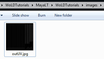
"outUV" screenshot JPG will be saved inside Maya LT/Maya project directory, in "images" folder:
Back in Photoshop:
Open "outUV" JPG screenshot and drag it into the Photoshop document. Make sure that "outUV" screenshot has the same width/height as the Photoshop document so you don't have to resize it.
We need to be able to see UV layout on top of the texture. If "outUV" image background is black: invert the layer. Select "UV Layout" layer and go to "Image > Adjustments > Invert" or press "Ctrl+I":
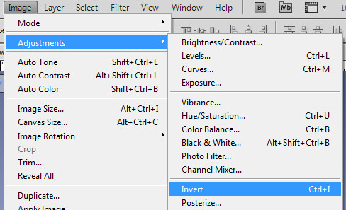

Position "UV Layout" layer on top of the layer stack and rename it. Set "Layer Blending" to "Multiply" and adjust "Opacity" as needed:

Also, open up baked Normal and AO map textures and place it into "Normal Map" and "AO" folders:

Step 24: Creating Albedo/Diffuse Texture
Create albedo/diffuse (base color map) texture.
There is a difference between an albedo and a diffuse texture.
Diffuse is a color texture used in non-PBR (Physically Based Rendering) workflow. Diffuse textures often have some light/shadow baked into the texture such as AO (Ambient Occlusion) and are often color/value corrected for specific lighting situation. Diffuse textures are not properly corrected for PBR (Physically Based Rendering).
UE4 uses PBR (Physically Based Rendering) lighting/shading model. This means all textures and materials will behave and react to light realistically and accurately like they would in the real world.
Albedo texture is what you want to create for Unreal Engine 4.
Albedo is PBR (Physically Based Rendering) correct "diffuse" texture with neutral base color of the object. Albedo textures should not contain any light and shadow information, no AO baked into the texture and it should be pure, neutral base colors of the object without any light/shadow.
Following the guidelines above, create an albedo (base color) map for your Static Mesh. There are many different techniques you can use to do this. Paint it manually from scratch, use photo images or combine photo images with manually painting.

The dark crevices in the two Albedo textures above are accumulated dirt and grime, not shadow detail.
Two software that are the current standard for creating Albedo textures are Quixel DDO and Substance Painter/Designer.
Save Albedo texture as PNG or TGA. I save mine as TGA, either 24 or 32 bit:
- 24-bit TGA (without Alpha Channel)
- 32-bit TGA (with Alpha Channel)
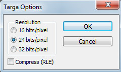
Make sure to hide "UV Layout" layer wireframe before saving so it doesn't show up in your final texture.
Step 25: Creating Detail Normal Maps
We already baked a normal map from high-poly to low-poly which defines overall form and shape of the model. But we do not have any surface texture detail within the baked normal.
You could sculpt this detail manually into your high-poly mesh with Mudbox or ZBrush then bake again but that would take a lot of time. A very common way to generate surface detail normal map is to use a photo image such as our albedo/diffuse texture and convert it to a normal map. Then combine your baked normal and surface detail normal into one final texture.
There are numerous software that can be used to convert 2d images to normal maps. These include Quixel NDO, xNormals Photoshop Filter, NVIDIA Normal Map Photoshop Filter, Substance, Knald, Awesome Bump and many others.
Detail Normal Map with NVIDIA PS Filter:
Download and install "NVIDIA Normal Map Filter" for Photoshop:
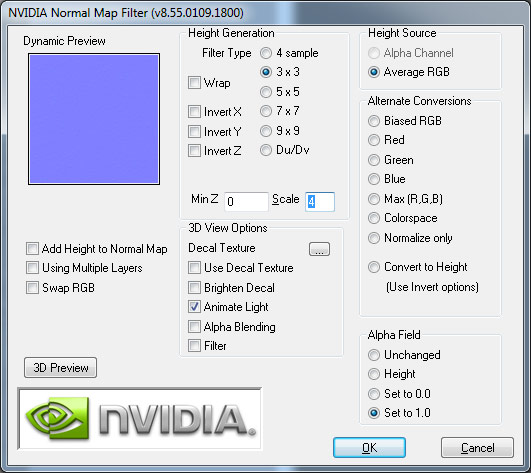
Open an albedo texture or any other 2d photo image and go to "Filter > NVIDIA Tools > NormalMapFilter":
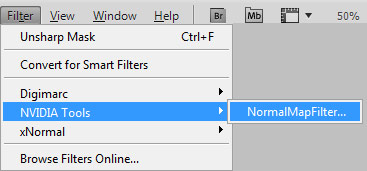
Set the following:
- Height Generation: 3x3 (lower value = sharper; higher value = more blur/smoother)
- Min Z: 0
- Scale: 4
- Height Source: Average RGB
- Alpha Field: Set to 1.0

Click "OK".
You now have detail normal map:

Detail Normal Map with Quixel NDO:
Quixel NDO is a great software that I use to generate Normal Maps.
Launch Quixel and NDO:

Open an Albedo/Diffuse texture or any other 2d photo image you want to convert. With NDO open go to "Settings > Photo-Normal Presets":

Choose a preset based on the type of surface property your texture is and click "Active Doc":
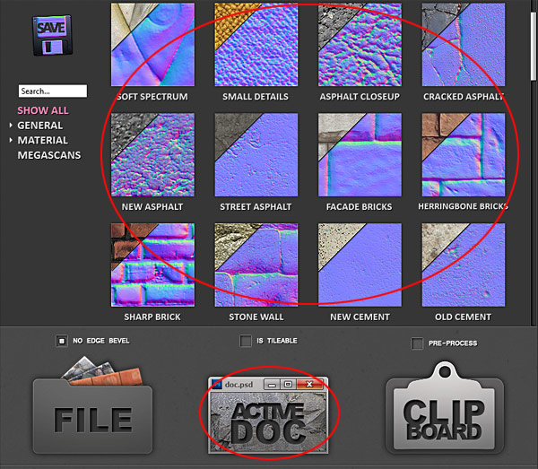
Adjust various settings for the generated normal map:

Final surface detail Normal Map:

Invert/Flip Green Channel
You may experience a Normal Map not displaying properly inside UE4. Incorrect display (left) and corrected display (right):

If this happens, you must invert or flip normal map's Green Channel in Photoshop or UE4.
First option is in Photoshop. Switch over to "Channels", select the "Green Channel" and invert (Ctrl+I) the "Green Channel":

Second option is to enable "Flip Green Channel" in UE4's Texture Editor:

We now have a baked normal map and detail normal map. We need to combine/blend them together into one single normal map texture.
Combine Normal Maps Manually in Photoshop:
Have both normal map layers inside a single Photoshop document. Detail Normal Map layer on top of baked Normal Map layer:
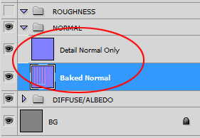
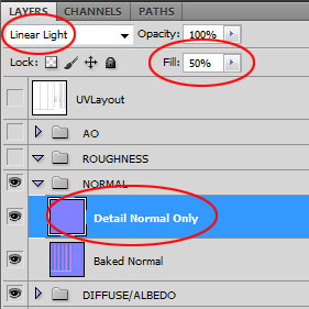
Select detail layer (top) and set "Fill: 50%" and "Blend Mode: Linear Light":
Double Click on the detail normal layer for "Layer Style" properties and enable "Blend Interior Effects as Group":

Enable "Style: Color Overlay" and "Blend Mode: Linear Burn":

Set color to "R = 255, G = 255, B = 128":
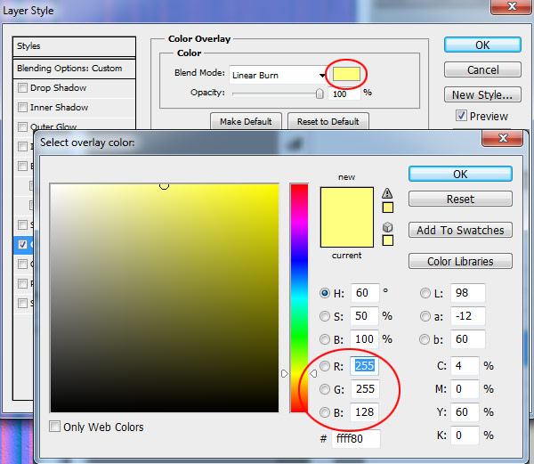
Click "OK".
Top "Detail Normal Only" layer will now be correctly combined with "Baked Normal" layer:

Combine Normal Maps with NDO:
Combining normal maps with NDO is extremely simple.
Open NDO. Place both Normal Maps inside a single Photoshop document. Detail normal map layer on top of base normal map layer:

Select detail Normal Map layer (top).
Go to "Settings" drop down menu and choose "Mix > Overlay Normal":

Detail Normal will now be combined with baked Normal map.
Combine Normal Maps in UE4:
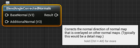
You could also import and blend 2 normal maps together inside UE4 "Material Editor" using "BlendAngleCorrectedNormals" node:
- BaseNormal: baked Normal
- AdditionalNormal: detail Normal
Saving/Exporting Normal Maps:
Save/Export Normal Maps as Targa (TGA) 24-bit:

Do not include an alpha channel with your normal maps in UE4. Unreal Engine 4 uses BC5 compression for normals maps which removes the Alpha channels on import.
Step 26: Creating Roughness Texture
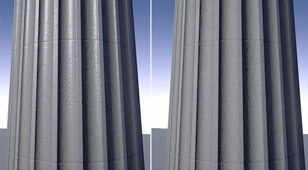
Roughness texture controls how rough or how smooth the surface is; how much light it reflects or absorbs:

Without or default Roughness (left) and with a Roughness map (right):
Roughness Texture Guidelines:
Some general and important guidelines for roughness textures:
- Rough surface will reflect less light (matte or less shiny)
- Smooth surface will reflect more light (more shiny)
- Roughness texture should be black/white values with various grays in-between
- White = rough (matte)
- Black = smooth (shiny)
- UE4 Constant1Vector can be used, set value between 0-1; 0 = Shiny (Black), 1 = Matte (White)
Creating Roughness Texture:
One of the quickest ways to create a roughness map is to use already created Albedo texture, desaturate it, adjust levels, brightness and contrast:
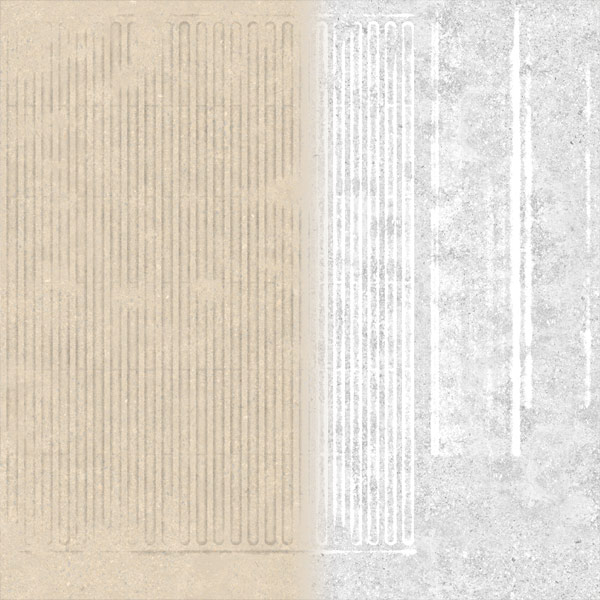
Remember white = rough (matte) and black = smooth (shiny).
Other ways to create Roughness texture includes manually painting it from scratch, use/adjust photo images, combine photo images and manual painting, use stock roughness textures or use Substance Painter, Quixel DDO.
Here are Quixel DDO generated Albedo and Roughness maps:
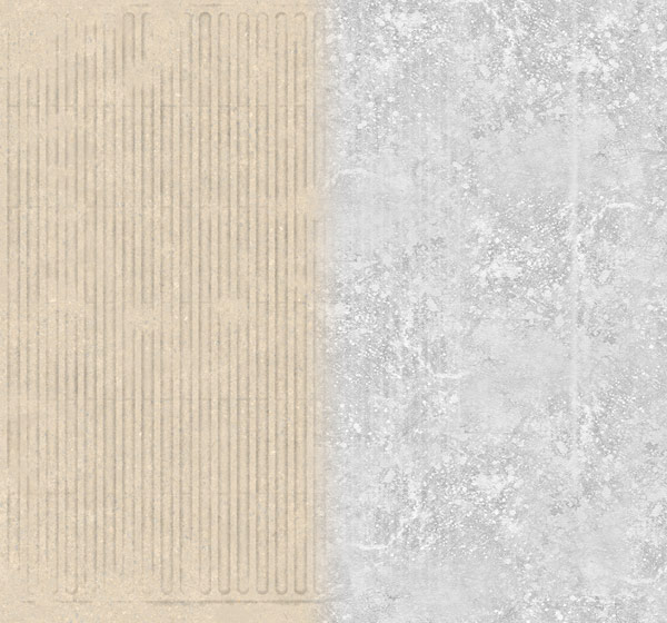
The amount of black and white will depend on your material type and how much light that object absorbs and reflects.
In UE4, open up "Texture Editor" for your Roughness map and disable "sRGB" in textures properties prior to inserting it as a "Texture Sample" node in Material Editor. Roughness will still work with "sRGB" enabled, but recommended and proper Roughness texture has "sRGB" disabled:

Step 27: Creating Metallic Texture
Metallic input controls how "metal-like" your surface is:
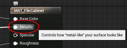
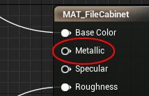
If your object isn't metallic, then leave "Metallic" input empty:
If your object is metallic, then use "Constant1Vector" with value of 1 to enable "Metallic":
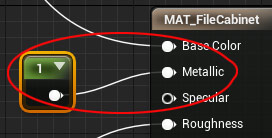
Most Static Meshes will either use "Constant1Vector" set to 1 for Metallic or nothing at all.
If you have an object that has a combination of Metallic and Non-Metallic, then you'll have to use a mask to let UE4 know which parts are metallic and which are not.
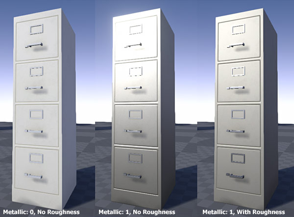
So, if your object is Metallic then use "Constant1Vector" set to 1 and then adjust "Roughness" for how shiny or how matte you want your metal to be. Here is a file cabinet prop with various properties:
Step 28: Creating Initial UE4 Material
Set up initial UE4 material to work with and apply it to your Static Mesh. The following settings are for most common hard-surface objects that do not include organic or moving materials. This setup is just a quick start and will vary greatly depending on material type.
Import all texture maps into UE4 that you'll use:

Disable "sRGB" property for Roughness texture in "Texture Editor":

If you are importing Masks texture and each Channel is packed using a Mask, then in "Texture Editor" enable "Compression Settings" to "Masks (noSRGB)":

Flip Normal Map's "Green Channel" if needed:

Use all imported textures and connect them to proper inputs:
- Albedo Texture > Base Color
- Constant1Vector > Metallic (1 = Metallic, 0 = Not Metallic)
- Roughness Texture > Roughness
- Normal Map Texture > Normal
- AO Texture > Ambient Occlusion

"Save" your material:

Assign the Material onto your Static Mesh:
- Open "Static Mesh Editor"
- In "Content Browser" select the Material
- Go back to "Static Mesh Editor"
- Click on the arrow to "Use Selected Asset from Content Browser"
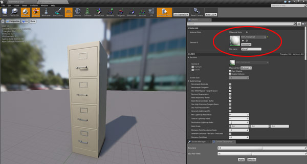
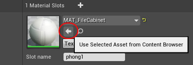
At this point you would begin to develop you material further using variety of nodes in UE4's "Material Editor".
Step 29: Testing Static Meshes
Perform this step throughout the entire Static Mesh creation pipeline. Constantly export and import the mesh to test inside Unreal Engine 4 to catch any problems early. After importing the Static mesh, use the reimport option by right-clicking on the mesh inside the "Content Browser" and choosing "Reimport":
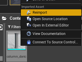
If you encounter problems using Reimport" option where the Static Mesh isn't updating, then import it as a new object by clicking "Import" and go through the importing options again.
"Build Lighting Only" or "Build" to check Lightmaps:

Jump into the map to test your Static Meshes. In "Perspective Viewport "Right-Click" and choose "Play From Here":

Continue to model, texture, develop materials, test, fix and reimport until the Static Mesh is completed.
How to Create Game Environment Assets for UE4 in 6 Easy Hours...
For more complete step-by-step tutorial series (6+ hours) on how to create, export and import custom Static Meshes, take a look at "UE4 Custom Static Mesh Formula".
Home Terms of Use/Trademarks/Disclaimers Privacy Policy Donate About Contact
All content on this website is copyrighted ©2008-2024 World of Level Design LLC. All rights reserved.
Duplication and distribution is illegal and strictly prohibited.
World of Level Design LLC is an independent company. World of Level Design website, its tutorials and products are not endorsed, sponsored or approved by any mentioned companies on this website in any way. All content is based on my own personal experimentation, experience and opinion. World of Level Design™ and 11 Day Level Design™ are trademarks of AlexG.
Template powered by w3.css


 Maya Foundation: Home-Study Course - Model and UV Environments
 Substance 3D Painter Essentials - Master Texturing
 UE5: Fundamentals Vol.1 - Create with Unreal Engine 5
 UE5: Retro Office Project - Create Beautiful Interior Env
 UE5: Master Material Creation - Create Master Materials in UE5