World of Level Design™
Tutorials to Becoming the Best Level Designer and Game Environment Artist (since 2008)
Workflow: Creating "Doric Column/Pillar" Game Asset with Maya LT/Maya, Quixel and UE4
Category: UE4, Maya LT/Maya, Game Environment Art
August 21, 2017

Pillar/Column is an essential prop for most game environments. They are some of the most common game assets you'll create.
The type of pillar/column created will depend on architecture style of the game environment but the workflow for creating these assets will be very similar.
Prior to creating any prop you have to decide what you are going to create and how you are going to approach creating it.
- What you are going to create: this is done through preproduction/planning and research
- How you are going to approach creating it: these are artistic and technical skills required to pull it off which are based on experience and a lot of practice; if you don't have much experience then going through tutorials like this will help
In this tutorial you'll see the entire workflow pipeline for a Doric style column/pillar.
If the tutorial workflow moves too fast, then you need this step-by-step pipeline "UE4 Custom Static Mesh Formula".
Software Used
I'll be using the following software:
- Maya LT: for modeling (Maya can also be used; Maya LT vs Maya and why I switched to Maya LT)
- Unreal Engine 4: for importing, lighting, testing and using the prop in the level
- Quixel Suite 2: for texturing
If you are using other 3d modeling software such as 3dsMax, Modo, Blender etc. you will still be able to follow and use this pipeline. For Quixel substitute you can use Substance.
Pipeline Overview
Let me show you the pipeline overview covered in this workflow tutorial.
I will begin with preproduction and planning. You will see this in almost all workflow tutorials on the website. Planning and preproduction is an essential part of the game environment and level design creation:

I'll set up project folder and insert character reference scale to help judge proportion of the meshes built in Maya LT/Maya and UE4:

I'll then start with a base mesh. This will be a simple low-poly object that will mimic the shape and size of the Doric pillar/column but will not be the final low-poly mesh I use in UE4. It will only be used for size and scale to help creating the high-poly mesh:

I'll show you two possible modeling methods for creating the high-poly mesh and which method produces superior results:
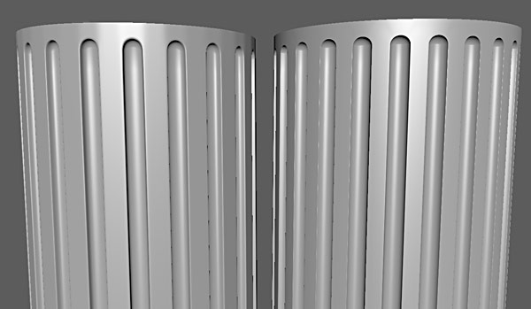
I will then create high-poly mesh of the pillar:
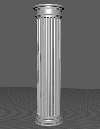
Next, I'll create low-poly version of the mesh to match high-poly version. This low-poly mesh will be used as the final in-game object:

UV low-poly for texturing:

I'll bake Normal and Ambient Occlusion maps:

Set-up material in UE4 and import Normal map and AO map:
Create detail Normal using Quixel NDO:

Create Albedo and Roughness texture using Quixel DDO:
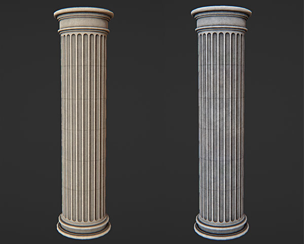
Create Lightmaps:

And finish off by creating custom collision:
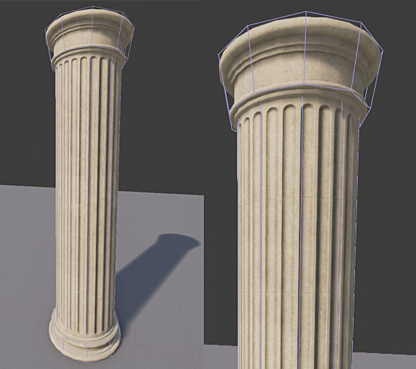
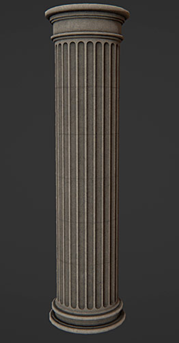
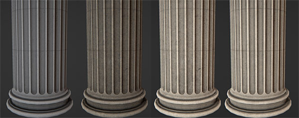
Final result is this Doric style column/pillar:

Preproduction and Planning
The amount of time you spend in preproduction/planning will depend on complexity of your game asset and how much time you have.
One thing for certain, you never want to skip preproduction/planning stage. A lot of questions came up for me prior to creating the Doric column/pillar:
- Is this going to be old or new pillar?
- Should I create low-poly or high-poly first?
- How do I create the column indent detail for high-poly? Which modeling method would work best?
- Should I sculpt high-poly in Mudbox or is sub-d modeling be enough?
- How will I create textures? Manual hand-painting or Quixel?
- What type of material will I need to create? What will be the look of it?
- How much detail should I include? Will the player see this prop up close?
- What will be the viewpoint of this prop? Is this for first-person, third-person, driving or top-down? This will determine the amount of detail I include.
Knowing the answers to these will depend on preproduction, research you've done and prior modeling/texturing experience.
I began collecting a lot of reference of Doric style columns. I also did research into different column styles such as Ionic and Corinthian but decided to stick with Doric due to time constraint.
Doric column is simpler in design to model then the other types.

From photo reference, prior experience and practice I decided on the following criteria:
- High-poly first, low-poly second to match high-poly
- Sub-d modeling, no sculpting
- Two versions of the column, one clean and one old; all done through textures using Quixel
- Viewpoint of this prop is first-person and will be viewed up close by the player
- Simple material using texture maps created in Quixel with possible detail textures for extra detail when viewed up-close
For texturing (my currently weak area) I went through additional tutorials and did a lot of practice. This had to do with using Quixel Suite, specifically DDO.
I'll be using high-poly to low-poly modeling method without sculpting. This means I'll focus on creating high-poly object first then create low-poly that will match high-poly in shape and size.
Some props will require you to create a high-poly first and low-poly second; while others low-poly first and high-poly second like we did in the file cabinet tutorial. Also some props may require sculpting and while others won't. All this depends on the game asset, your experience and time to deadline.
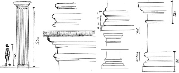
After collecting reference and research, I did a few sketches to help me understand the shape and silhouette of the pillar better:
Project File Set Up
I already set up project folders for Maya LT/Maya, UE4 and textures. These folders keep all the content organized and in one place. See the following tutorial for more info on how I did this.
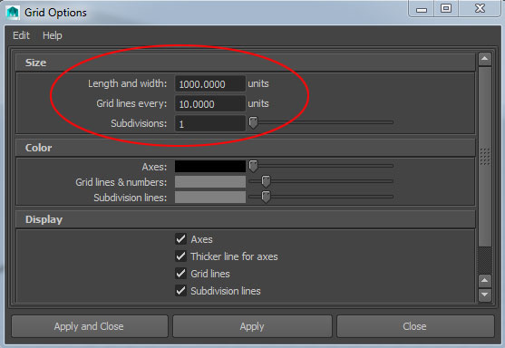
It is important to set up your grid in Maya LT/Maya so it matches UE4:
Scale Reference and Environment Proportions
For both Maya LT/Maya and UE4 I set up player reference scale to help me judge proportions better.
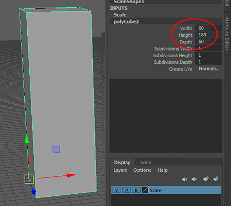
In Maya LT this consists of a simple cube with the following dimensions:
- Height: 180
- Depth: 60
- Width: 60
In UE4 I use "UE4 Mannequin: Mobile". Default character dimensions in UE4 are:

- Height: 180
- Depth: 40-60
- Width: 40-60
Creating the Base Mesh
I need to create a base mesh to judge scale and size of the pillar. This mesh will eventually be discarded but right now it is an important object to help determine the dimensions I like.
I use a cylinder with the following dimensions:
- Radius: 50
- Height: 500
- Subdivision Axis: 24

I also need to create the bottom and top base of the pillar. Based on preproduction, I estimate that I want the bottom section to be 30 units tall and top section 50 units tall.

I create new cylinder for bottom at 30 units in height:
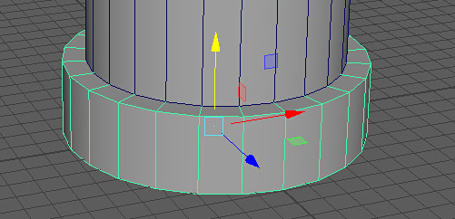
And top at 50 units in height:

I quickly export what I have so far from Maya LT using "File > Export Selection":

Name the file and make sure "File of Type" is set to "FBX export":

I use FBX with following settings:
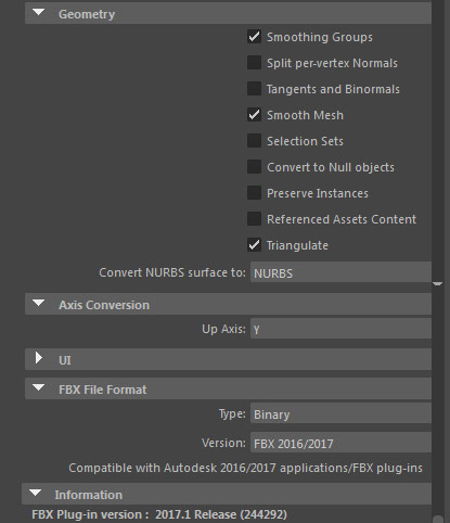
I will use these settings for the rest of the tutorial.
Import the base mesh into UE4 using the following settings. I've disabled:
- Auto Generate Collision
- Generate Lightmap UVs
- Import Materials
- Import Textures
Everything else was kept at default.

I like the size and scale of the mesh:

Back in Maya LT, I add more geometry to the bottom and top sections. I want to see what it would look like:

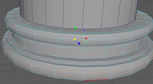
I am keeping this step very simple. I am focused on creating the base mesh to reference correct scale and size. So I don't spend much time here because final low-poly will be re-recreated from scratch to fit high-poly.
Base mesh reimported in UE4:

It is time to start on high-poly mesh. There are 2 ways I can approach modeling indents or middle section of the Doric style column. These parts right here:

From a quarter capsule or from extruded faces.
Knowing which method is better and which you should use will come from experience and constant practice. But let me show you what these 2 methods are and the one I end up using.
High-Poly Modeling Method #1 (Extruded Cylinder Faces)
Most obvious and straight-forward method to model the pillar indents would be to create a cylinder with a lot of "Subdivision Axis" segments:
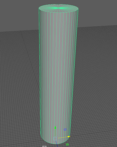
Select every other face, offset and extrude:

Add more geometry:

Adjust indented faces:

Preview Smooth:
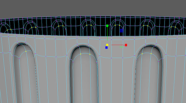
Rework the mesh to add supporting edge loops so the high-poly mesh doesn't collapse when smoothed and final result for the pillar indents:


With a bit of work, it creates decent results. But there is a better way which produces far more superior result and higher quality Normal map bake.
High-Poly Modeling Method #2 (From Quarter Capsule)
Second modeling method will create far more superior results. It includes using a quarter of a capsule (which comes from a quad sphere), creating a single indent, duplicating that indent and applying a Bend deformer to create the cylindrical pillar.

Let's go through a step-by-step on how to achieve this.
Step #1 - Create Quad Sphere:
I need a perfect quad sphere to get this shape:

There are different ways to make a quad sphere. The best way I've found is as follows.
I create a cube with dimensions for "Width/Height/Depth: 100". The size doesn't matter because I will end up resizing the final sphere but I need something to start with and 100 units is what I used. I also set "Subdivision" for "Width/Height/Depth" all to "8":

Then, create a sphere with "Radius/Subdivision Axis/Subdivision Height" set to "50":
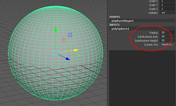
Place the sphere inside the cube. Make sure it is completely inside:

Dimensions I used are perfect to make the sphere fit inside the cube but you can manually scale the sphere or the cube.
Select the sphere first and the cube second, the order of selection is very important:

Go to "Mesh > Transfer Attributes" options:

Set the settings to:
- Vertex Position: On
- Vertex Normal: On
- UV Sets: Off
- Color Sets: Off
- Sample Space: World
- Mirroring: Off
- Search Method: Closest to Point

Click "Transfer".
The attributes from the sphere are transferred to the cube:

Select both objects and "Delete History" (Alt+Shift+D):

Delete the original sphere and you will be left with a perfect quad sphere:

Step #2 - Creating Pillar Indent:
Delete all but 1/4 of the quad sphere:

I need to have the inner capsule faces visible and outer faces invisible. For this I need to reverse normals. Select the object and go to "Mesh Display > Reverse":
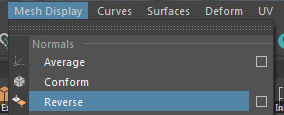
This reverses the normals:
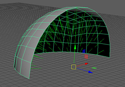
But the shading display of the faces in Maya LT is still the same. Fix this by going to "Mesh Display > Unlock Normals":
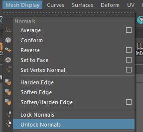
Now the shading is correct:

Next I set the grid size to 15 units:

And scale the quarter of the capsule to fit inside those 15 units:

15 units is how wide I want each indent segment to be. I choose 15 units based on previous attempts at modeling this. I tried 10 units and it was too small and 15 units size was perfect.
I select border edges in front but not on the bottom of the mesh:

Extrude the edges:
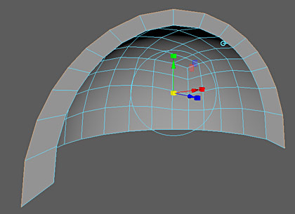
And align them to the grid:
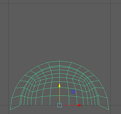

Select bottom edges and extrude down:

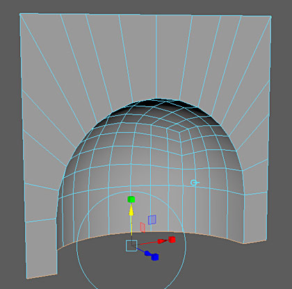
If I smooth the object now, there is no definition:
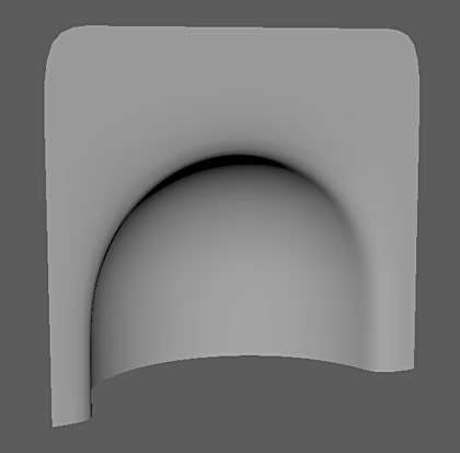
I need to bevel inner edges. I select those edges:

And "Edit Mesh > Bevel":
- Fraction: .2
- Segments: 2
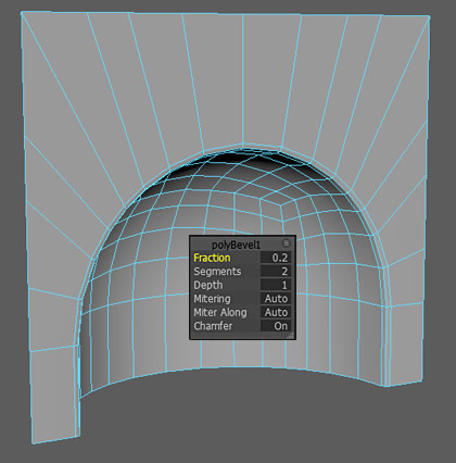
Press "3" to preview Smooth, which produces good results:

Press "1" to go back to low-poly view.
I test how these segments would look next to each other by duplicating them a few times:

I did a couple of tests to see which one looks better. You might have to go through a few a few iterations yourself to find what looks best. Based on reference and the version I like better, I choose the one on the top, with bigger indent:

I now need to mirror the mesh to complete the indent segment. I modify the pivot point to the bottom of the mesh; this is important for mirroring:

Then go to "Mesh > Mirror" options:

In the options I set (options may be different for you):
- Mirror Axis: Y
- Mirror Direction: -
- Combine with Original: enabled
- Border: Merge border vertices
- Merge Threshold: Automatic
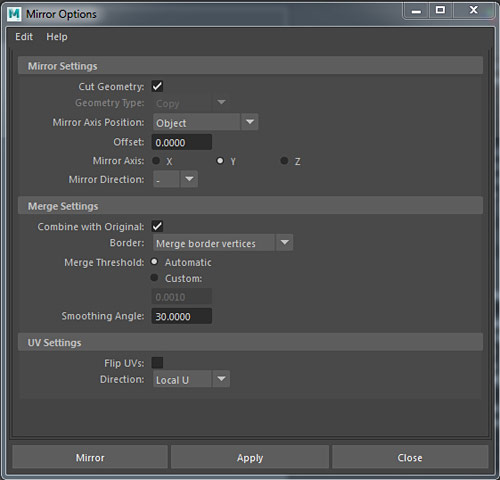
Make sure to "Delete History" after using "Mirror" command.
Here is mirrored indent segment:

I select bottom set of vertices:

And move them all the way down so the entire height of the indent segment is 500 units:

Use scale base mesh for size reference:
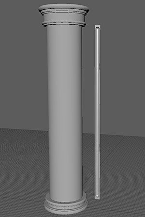
Each half indent segment is 15 units in width and 500 units in height.
I positioned the pivot point at the top left of the mesh to make it easier to duplicate:
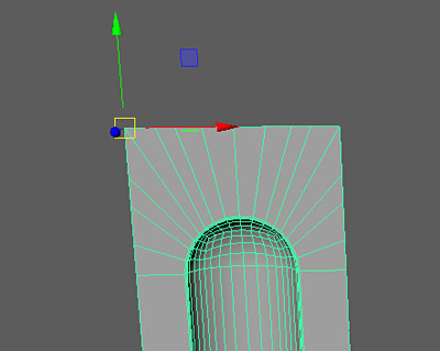
Duplicate the indent segment 23 times, for 24 total segments:

Select all segments and go to "Mesh > Combine":

I make sure to merge vertices between each duplicated indent, select them first:

Go to "Edit Mesh > Merge":

Step #3 - Applying Bend:
Right now I have a flat wall surface with all indents of the pillar:
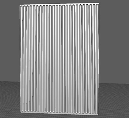
I will be using "Bend" deformer to create the column shape. This technique can be used for variety of geometry and I highly recommend to experiment using this.
Select the mesh and go to "Deform > Nonlinear > Bend" options:
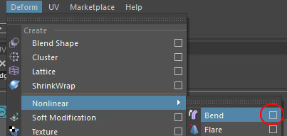
Set the following:
- Low bound: -1
- High Bound: 1
- Curvature: 230 (I will adjust this value in the channel box later)

Click "Create".
The results will look like they are unusable:
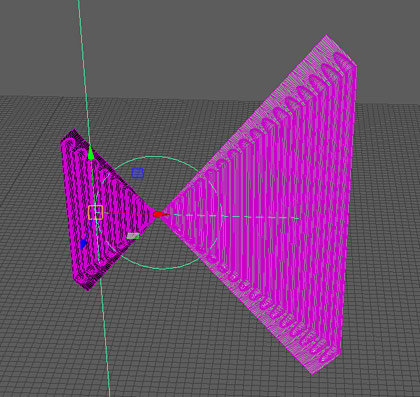
To make this work, go to "Channel Box" and adjust "Rotate X and Y" to "90":
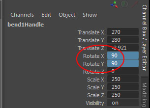
It is beginning to look like a pillar now:

Now let's adjust "Curvature" setting to close the gap. In the "Input" tab I change "Curvature" to "249.8":
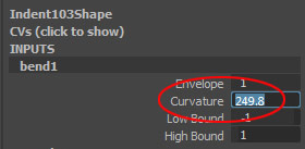
This is as close as I can get the curvature to work without overlapping. Select all the vertices within the gap and merge them, thus closing the gap:
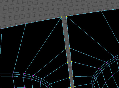


"Delete History" to remove "Bend" deformer from construction history and press "3" to preview Smooth:

One more part I need to create is slight extrusion and angle on the bottom and top of the columns like you see here in the reference:

I will need to adjust geometry on the bottom and top of the mesh to create space for extrusion so I can still maintain 500 unit height. I should have done this earlier, during the indent modeling. But often you'll have make unplanned changed and rework you model along the way.
I select bottom vertices and move them up:

Then, select bottom edge and extrude a couple of times:
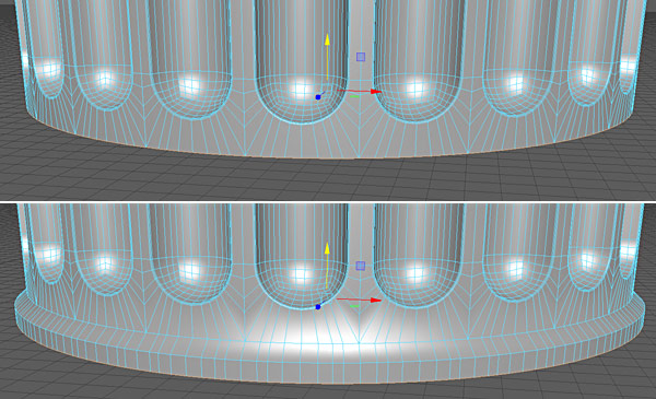
Insert supporting edge loops:

And Smooth preview to see what it looks like. Here is before and after supporting edge loops:
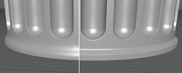
I also make sure to align the bottom edges to the grid line:

Instead of repeating the same step for the top, I decide to mirror. I cut the column/pillar in half and delete the top:

Modify the pivot point to top and middle of the mesh:

Then go to "Mesh > Mirror" options and set the following:
- Mirror Axis: Y
- Mirror Direction: +
- Combine with Original: enabled
- Border: Merge border vertices
- Merge Threshold: Automatic

Now I have perfectly symmetrical middle section:

Step #4 - Extrude Top/Bottom Bases:
It is time to begin building the bottom and top sections of the pillar.
I select bottom edges and begin to extrude to create bottom section. I pay attention to my photo reference and sketches to guide me:

Here are values I used for extruding bottom section edges:
- Thickness: 5
- Local Translate Z: -7.5
- Thickness: -2
- Local Translate Z: 2.5
- Thickness: -2
- Local Translate Z: 9
- Thickness: 5
- Local Translate Z: -2.5
- Thickness: 4
- Local Translate Z: -8.5

The bottom section is 30 units in height and the bottom edges have to snap to the ground grid plane:

I insert few more edge loops:

And scale those edges out to add curvature:

I then insert supporting edge loops to make the bottom section Smooth properly:

After applying Smooth, here is what the pillar looks like with and without supporting edge loops:
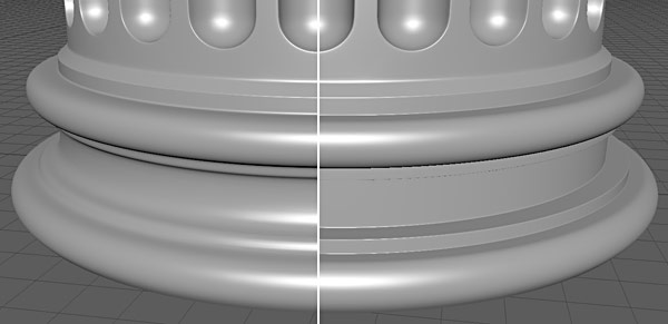
After the bottom section is done I move to the top. I select top edges and begin to extrude. The shape I end up with:

Here are values I used for extruding top section edges, which has to total 50 units in height:
- Thickness: 3
- Local Translate Z: -6
- Thickness: -3
- Local Translate Z: 23
- Thickness: 3
- Local Translate Z: -3.5
- Thickness: 3
- Local Translate Z: -6
- Thickness: 4
- Local Translate Z: -11.5
I make sure that top edge is snapped to the grid line:
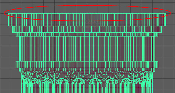
Insert additional edge loops:

And scale those edges out to add curvature:
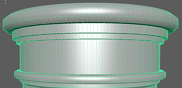
Insert supporting edge loops to make the bottom section Smooth properly:

After applying Smooth, here is what the pillar looks like with and without supporting edge loops:

Important: every time I used "Local Translate Z" I set the gizmo to "World" by clicking on the light blue icon:

High-poly mesh is now completed:

At this point you could take this mesh into Mudbox or ZBrush and begin sculpting. I won't be doing this due to time. Although this process will be focused on in another tutorial.
Step #6 - Apply Smooth:
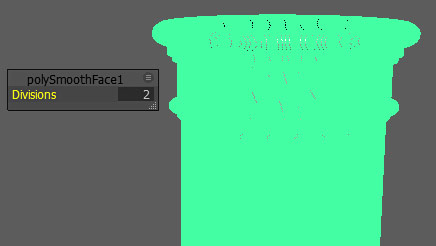
"Delete History" on high-poly mesh and apply "Mesh > Smooth" with "Divisions: 2":
Creating Low-Poly
I will re-create low-poly to match high-poly. I could use base mesh created earlier, but instead I will start from scratch.
I extract top, bottom and middle sections of the high-poly pillar to be their own objects. This way I can hide them from view and focus on one section at a time. I will combine them back later.
You don't have to do this. I am only doing this for clarity of this tutorial.
I select faces for the middle, top and bottom sections:
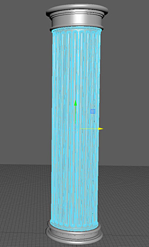
Go to "Edit Mesh > Extract":

I end up with middle, top and bottom as separate objects:
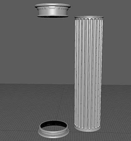
I move top/bottom sections out of the way and focus on creating the middle low-poly section first. I create a new cylinder to match the high-poly using following values:
- Radius: 50
- Height: 500
- Subdivision Axis: 24

Essentially this is what I started with, but the radius of low-poly pillar doesn't match the high-poly. I increase the radius to 60:
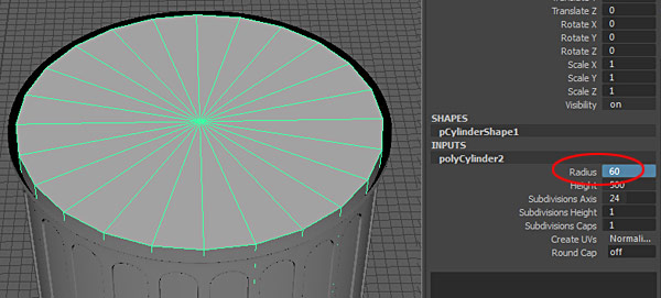
10 more units isn't going to make this pillar disproportionate and I actually like thicker look of the column.
I insert 2 edges at the top:

I scale the faces out to match the high-poly:

I use the high-poly mesh as reference for my low-poly. To do this I placed high-poly mesh into a "Display Layer" and set that layer to "T" for template:
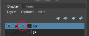
Instead of redoing the same thing for the bottom, I delete half of low-poly mesh:

And mirror:

"Delete History" and now I have low-poly, middle pillar section:

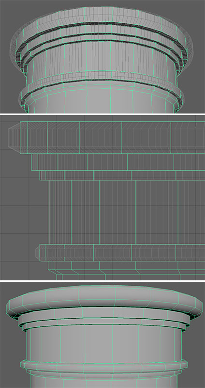
For the bottom and top base sections, I extrude edges like I did on the high-poly. I use the same input values for edge extrusion to match low-poly to high-poly. Of course you can manually extrude without remembering exact values you used before.
Here is the bottom after extruding the edges to match high-poly:
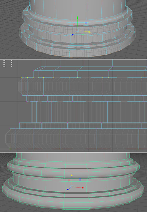
I do the same thing for the top:
I add faces at the top and bottom of the mesh using "Append to Poly Tool":

Name the low-poly mesh to "column_LP":
![]()

I now have high-poly and low-poly that are the same shape and overlap each other, which is what I need to bake Normal and Ambient Occlusion maps later on.
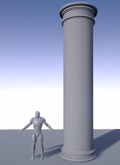
I re-export and re-import the low-poly to see what it looks like in UE4:
Unwrap Low-Poly
I need to unwrap the low-poly mesh for texturing, prior to baking Normal and AO maps. You don't need to unwrap high-poly, unless painting textures in ZBrush or Mudbox.
I create new "phong" shader, assign "UVGrid" texture and apply the shader onto low-poly mesh:
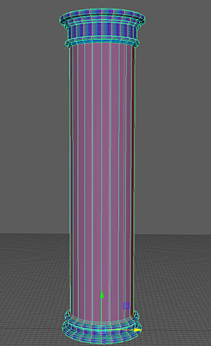
This helps me to see where texture stretching and distortions are. I could have used texture checker option in "UV Editor", but I like using "UVGrid" texture instead.
I select middle base section faces and use "UV > Cylindrical" mapping. I do the same for the top and bottom sections:
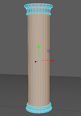

Unwrapping as it is now and it is a good start:


There is significant stretching at the bottom and top sections of the pillar:

Also there is slight stretching on the middle, bottom part as well:

I select middle section UVs:

Use "Unfold" within "UV Toolkit":
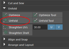
Unfold fixes the stretching but makes the UV shell not straight:

I select all UVs and choose "Straighten UVs":
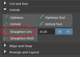
UVs in the middle section now look good:
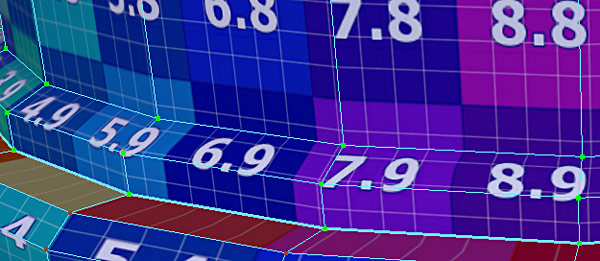
Bottom section UVs need a lot of work:

Select the bottom section UVs:

Run "Unfold" from "UV Toolkit" inside "UV Editor":

Then "Straighten UVs":

Straight UVs will make it easier for me to texture and bake Normal maps, rather than leaving them as curved UVs.
The top section took a bit more time; I had to run "Unfold Tool", "Unfold" and "Straighten UVs" a couple of times to make it work:

At first, "Unfold" and "Straighten UVs" gave me this result:

It finally worked after repeating "Unfold Tool", "Unfold" and "Straighten UVs" few times while selecting all UVs and then certain UVs at a time:

I then layout UVs the following way:


Set Hard/Soft Edges (Smoothing Groups)
Hard/Soft edges are also known as Smoothing Groups. These determine which edges of your low-poly mesh appear hard and which appear soft.
Majority of this pillar will have soft edges but there are few areas where I want to maintain hard edges. I enable "Toggle Soft Edge Display" by "Hold Shift + Right Mouse Click" and choose "Soften/Harden Edge > Toggle Soft Edge Display":
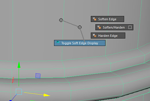
- Dashed lines: soft edges
- Solid lines: hard edges
I select the mesh and go to "Mesh Display > Soften Edge" (you can use the "Hold Shift + Right Mouse Click" shortcut):

This sets the entire object to have soft edges.
I then switch to Edge component mode and set following edges:

To hard edge, "Mesh Display > Harden Edge":
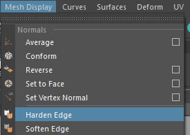
Important Concept: it is important to understand that where you have UV split or a hardened edge, the vertex count is doubled along those edges. There is a lot more to this concept but for now know that hard edges and UV splits/seams double vertex count in UE4.
Finish UVs
After setting hard/soft edges I need to revisit my UV layout.
Hard/soft edges determine where I should make cuts and separate UV shells. Hard edges that are still connected will often produce a Normal map artifact during the bake. Not always but as a rule of thumb, hard edges should be cut and separated into their own UV shell.
So if I bake Normal maps as is without cutting and separating UVs along hard edges, there will be a noticeable artifact along those edges.
I cut and separate hard edges to be their own UV shell:

The Normal map texture will bake cleaner.
Combining High-Poly
I extracted top, bottom and middle sections of the high-poly mesh as individual objects for clarity of the tutorial. I could keep them separate but for baking purposes it will be easier to keep track of a single high-poly mesh rather than 3 separate ones.
I need to combine 3 extracted objects into one. I select all high-poly sections:

Go to "Mesh > Combine":
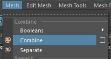
Then merge overlapping, doubled vertices between middle, top and bottom sections:

I use "Merge Threshold: 0.0001" to merge vertices that are on top of one another:

Name the high-poly mesh "column_HP":
![]()
Baking Normal Maps
I am now ready to bake Normal maps. Low-poly has been modeled, UVed, hard/soft edges set, high-poly created and smoothed.
I position high-poly to overlap low-poly mesh, on top of each other:

I will be using Maya LT/Maya Turtle Baker but you can use other baking software, such as xNormals.
To bake Normal maps in Maya LT, I follow a 3-step process:
- Set Bake Layers
- Set Bake Settings
- Bake Normal maps
Step 1: Set up Baking Layers
Open "Bake Layer Editor" by going to "Windows > Material/Texture Baking Editors > Turtle > Bake Layer Editor":

Create "New Layer" and rename the layer to "ColumnBake":

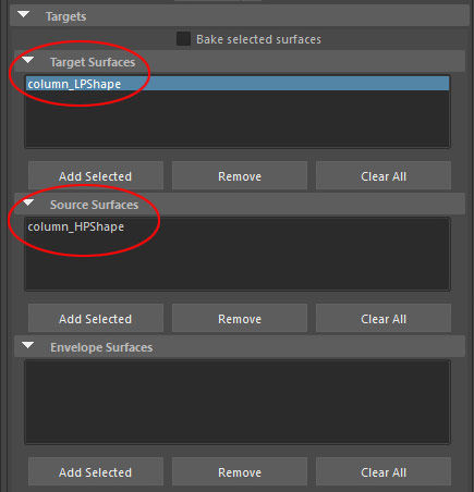
Add low-poly under "Target Surfaces" and high-poly under "Source Surfaces":
- Target Surface: low-poly object
- Source Surfaces: high-poly object

Step 2: Texture Baking Settings
Open "Texture Baking Settings" by going to "Windows > Material/Texture Baking Editors > Texture Baking Settings":
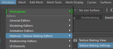
Enable "Bake":

Under "Sampling Tab: Anti-Aliasing":
- Min Sample Rate: 1
- Max Sample Rate: 2 (when doing a final bake I change this value to "4")

I switch to "Baking" tab, choose which baking layer to bake and set "Bake To: Texture":

"Target Surfaces" and "Source Surfaces" will be set from "Bake Layer Editor" and "Envelope" will be empty":
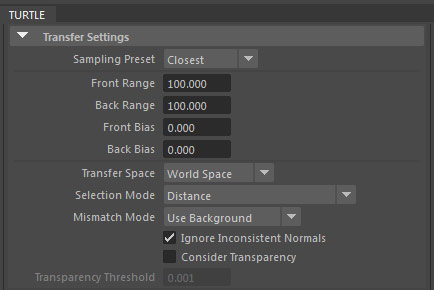
I then set the following "Transfer Settings":
- Sampling Preset: Closest
- Front Range: 100
- Back Range: 100
- Front Bias: 0
- Back Bias: 0
- Transfer Space: World Space
- Selection Mode: Distance
- Mismatch Mode: Use Background
- Ignore Inconsistent Normals: enabled
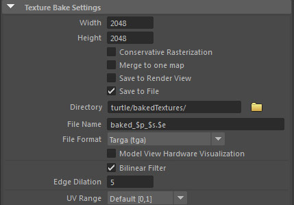
"Texture Bake Settings":
- Height/Width: 2048x2048
- Save to File: enabled
- File Format: TGA
- Bilinear Filter: enabled
- Edge Dilation: 5 (edge padding)
- UV Range: Default (0,1)
Under" Outputs: Shader Outputs" switch to "Normal Map" and disable everything else:
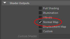
Under "Advanced Settings: Normal Map" set "Coordinate System" to "Tangent Space":

Step 3: Baking
Go to "Windows > Material/Texture Baking Editors > Texture Baking View":
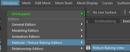
"Texture Baking View" window will pop up. Click on "Bake (Turtle)" icon:
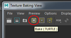
Normal map will now be baked:

You'll find all baked maps inside Maya LT/Maya project folder, "\turtle\bakedTextures":

Baking Ambient Occlusion
Ambient Occlusion will help to add shadowing into pillar's crevices, making it look better. Ambient Occlusion map will also be used to help texturing in Quixel's DDO.
I have low-poly that still overlaps high-poly:

Steps for baking Ambient Occlusion map are almost identical as baking a Normal map, except "Outputs: Shader Outputs" I switch to "Custom Shader" and click on checkered icon next to "Custom Shader" input:
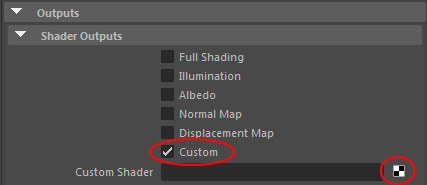
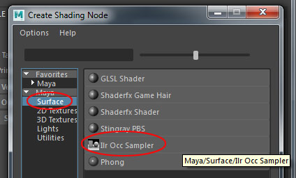
"Create Shading Node" menu will pop up. Select "Surface" and choose "Ilr Occ Sampler":
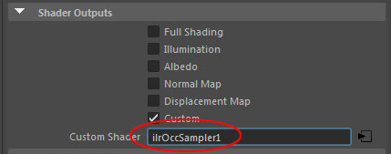
"Custom Shader" input will now have "ilrOccSampler1":
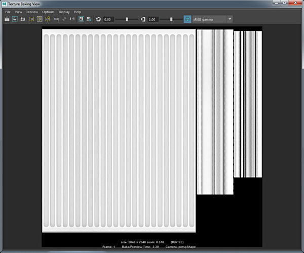
Go to "Texture Baking View" and bake Ambient Occlusion:
You'll find AO map inside Maya LT/Maya project folder, "\turtle\bakedTextures":

Photoshop Texture Document Setup
In Photoshop, I create a new document "File > New" with "2048x2048" pixel size:

Then, I create 4 folders:
- AO
- Roughness
- Normal
- Diffuse/Albedo

I need to bring in "UV Screenshot" into Photoshop which will give me UV wireframe layout so I know what I am texturing. In Maya LT, I open "UV Editor" and go to "Image > UV Snapshot":

I set the following options:
- File name: OutUV
- Size X: 2048
- Size Y: 2048
- Image format: JPEG
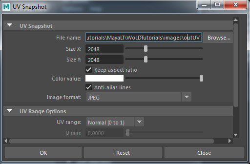
Click "OK".
"OutUV" screenshot was saved into Maya LT/Maya project folder, inside images folder:
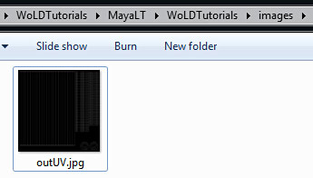
I place the UV screenshot into the texture Photoshop document at the top of the layer stack and press Ctrl+I to invert the image so blacks become white and whites become black:

I then rename the layer to "UVLayout", set layer "Blend Mode" to "Multiply" and lower "Opacity" to "75":

I bring it baked Normal and Ambient Occlusion map into this texture document as well:
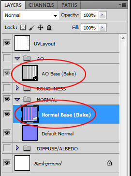
I save Normal and Ambient Occlusion maps as 24-bit Targa. This is what I will import into UE4:
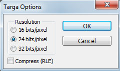
File naming I use:
- ColumnDoric_N
- ColumnDoric_AO
Make sure to disable the visibility of the "UVLayout" layer to hide the wireframe so it doesn't show up in the texture.
Re-Export/Re-Import the Static Mesh
I re-export the Static Mesh from Maya LT to make sure it is the most current version available to be imported into UE4. I run through the same commands as before, select the mesh and go to "File > Export Selection":

Or you could also use "File > Send to Unreal: Selection" if you've set up Unreal Project to export to:

FBX Geometry export options (same as before):

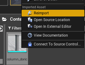
In UE4, I re-import the Static Mesh:
UE4 Initial Material Setup
I create a new material:

And name it "MAT_ColumnDoric":

I open Material Editor and insert "Constant3Vector". I use ".5" for RGB values to give me medium gray value:

I want a neutral solid color to use for "Base Color" until I create and import an Albedo map. Having something for Base Color will remove the default checker texture and allow me to see the Normal and Ambient Occlusion maps better.
I open "Static Mesh Editor" for the column:

And assign "MAT_ColumnDoric" material into "Material Slot" by clicking "Use Selected Asset from Content Browser":

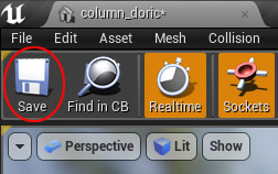
Click "Save":
Importing and Using Normal/AO Texture Maps
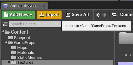
Import Normal and Ambient Occlusion textures by clicking "Import" in the Content Browser:
Navigate to the folder where final textures were saved, select them and click "Open":
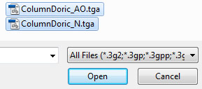
Imported textures:

Double-click on the Normal map in the "Content Browser" to open "Texture Editor":

Enable "Flip Green Channel" to make sure the Normal map is displayed correctly:

This could also have been done in Photoshop by inverting the Normal map's Green Channel.
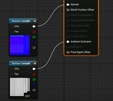
I bring in both textures, Normal and Ambient Occlusion into the "Material Editor" for the pillar as "Texture Sample" nodes and connect them to "Normal" and "Ambient Occlusion" inputs:

Click "Apply" and then preview in perspective viewport (Left to Right: Constant3Vector, with added Normal Map, with added AO):


Static Mesh/Normal Map Adjustment and Rebake
After looking over photo reference I decided to add slight segment separation within the column middle section. The middle part of the column is usually not a single solid piece but multiple segments combined together, as you can see it here:
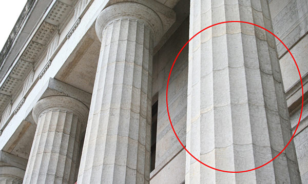
I have 3 options:
- Leave it alone and do nothing
- Add this detail into the Normal map using Quixel or NVIDIA Photoshop Filter
- Go back to Maya LT, model geometry detail into high-poly mesh and rebake to get new Normal and Ambient Occlusion maps
I decided to model it in and rebake. I duplicate high-poly mesh so I can revert back to original high-poly if needed.
Insert 10 edge loops:
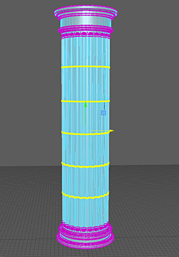
Here is a close-up of what that looks like:

Select the faces and extrude them:

I use the following extrusion values:
- Thickness: -.2
- Offset: .1
I add supporting edge loops so the high-poly mesh doesn't collapse. Here is before and after adding support edge loops:
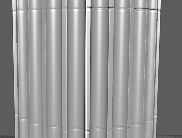
I then rebake to generate a new Normal and Ambient Occlusion map:

Here is the Static Mesh before added segments and after in UE4:
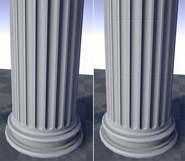
I like the new addition. It is very subtle, but looks better. Quixel DDO will help to bring this out even more.
Now if I didn't like how it looked, I would just revert back to the previous Normal map.
Creating Detail Texture Normal Map with NDO
Baked Normal map defines overall form and shape of the model. I now need object surface detail that would be seen on a stone pillar like this. I will use Quixel NDO to generate this surface detail.
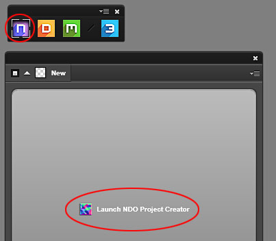
Open NDO and "Launch NDO Project Creator":
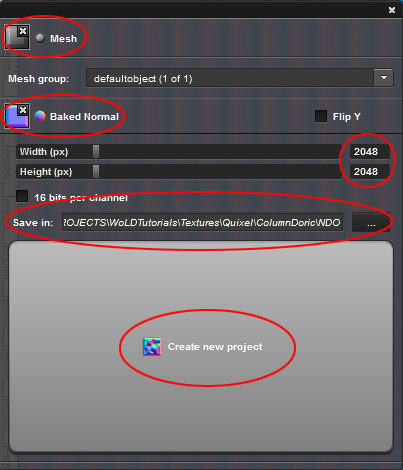
Plug-in exported "column_doric" model into "Mesh" input, baked Normal map into "Baked Normal" input, set Width/Height to "2048x2048" and "Create new project":
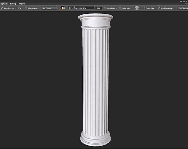
Load up "3DO" to see the preview of the mesh:
I open a new texture "ConcreteBare0418", downloaded from Textures.com:

I will use this image to generate Normal map surface detail. But before doing that, I need to do some prep work.
I crop the texture to 1024x1024 and desaturate it so it's black and white (Ctrl+Shift+U):
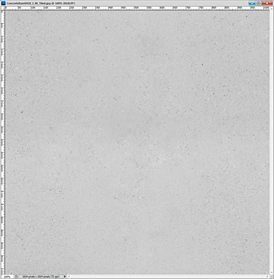
Apply "Filter > Offset" and use "Healing Brush Tool" and "Clone Stamp Tool" to make the texture tileable. I bring this tiled texture into NDO Normal map document:

And duplicated 3x to fill the entire canvas:
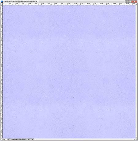
Then click here to convert the selected layer to a Normal map:

I change the "Blend Mode" to "Overlay" to blend this Normal map with my baked Normal:

Current default results:

And adjust NDO Normal map settings:

Adjusted Normal Map detail with Overlay:

Here are results without and with added surface detail Normal:
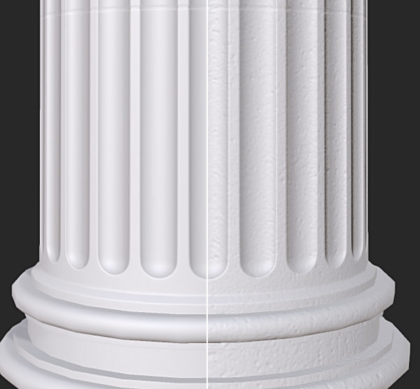
I now have a baked Normal and surface detail Normal as one texture. I save this Normal map as 24-bit Targa.
I reimport the Normal map into UE4 to see what it looks like:

I could have just converted a diffuse image to a Normal map without having to load the mesh or baked Normals into NDO. But it does allow me to see surface detail of the converted Normals on the mesh without having to export it into UE4 to see what it looks like on the Static Mesh.
Updating Ambient Occlusion Map
I should also update Ambient Occlusion map to include surface detail. I use the converted surface detail Normal without baked Normal map:
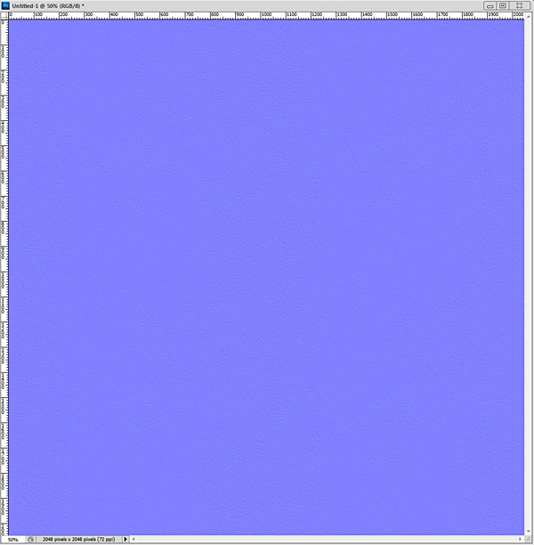
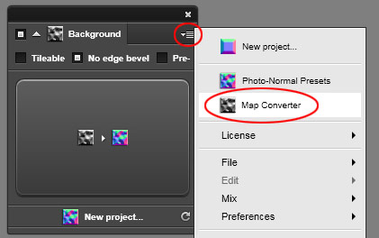
With NDO still open, I go to options and choose "Map Converter":
Choose "AO" and "Active Doc":
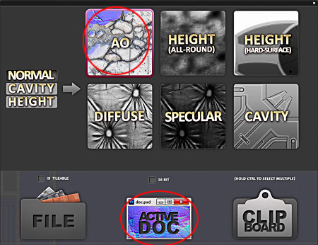
Results:

I use "Blend Mode: Multiply" to blend this Ambient Occlusion detail over my baked Ambient Occlusion from Maya LT.
Here is the before and after (baked AO from Maya LT on left, 2 AO maps combined together on right):
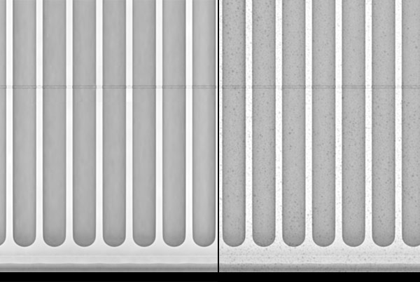
I save this new Ambient Occlusion and reimport it in UE4.
Creating Albedo and Roughness Texture with DDO
It is now time to create an Albedo and Roughness textures. I will be using Quixel DDO to do this.
Open DDO and assign the following:
- Mesh: exported mesh
- Normal: baked normal with surface detail created in last 2 steps
- AO: baked OA and with added detail created in last step
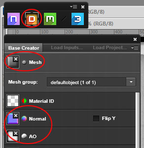
Enable "Bake in 3DO" for:
- Object Space Normal
- Curvature
- Position Gradient
These will allow DDO to know where to place various weathering and decay detail into your texture.
I set resolution to "4096x4096" but will end up sizing it down to "2048x2048" in the final texture. I set "Export Target" to UE4:

I could also use "UE4 RMA Packed" option. RMA stands for Roughness - Metalness - Ambient Occlusion and this will pack each texture into a Red, Green, Blue channels.
Set where you want to save DDO project in and Click "Create":

If you get the option box to "Keep Layers", "Cancel" or "Flatten", choose "Keep Layers". Anytime I chose to "Discard" or "Cancel" I wasn't able to add any materials in DDO:

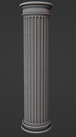
Open up "3DO" to see your mesh:
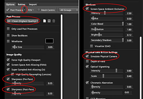
Set up "Post Processing" to view the Mesh with better quality. I enable:
- 03 - Clean (Highest Quality)
- High Quality Resampling (Lanczos)
- Sharpness (Pre-Pass)
- Sharpness (Post-Pass)
- Screen Space Ambient Occlusion
- Simulate Physical Camera
I click on "Add Smart Material":

And choose "New Concrete" and click "Create":

Here is default "New Concrete" material:
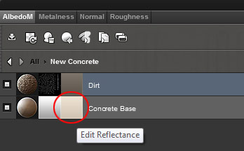
Click on "Edit Reflectance" to change color of "Concrete Base" to a lighter value:

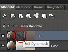
For "Dirt" layer, click on "Edit Dynamask":
Update to use "Dirt" mask preset and click "Accept Mask":

I could spend hours in DDO, trying different materials and manually painting dirt/weathering masks. But I will call this done.
Here are before and after progression from base color to adding dirt mask:
click on image to view full size
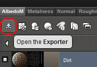
I need to export my texture maps. Click on "Open the Exporter":
I set the following properties:
- .tga
- 8 bit
- 50% (textures will be resized from 4096 to 2048)
- Sharper
- Export Target: UE4

Click on "Export This Material".
You will find all saved textures in the same folder directory where you saved the DDO project into, inside "Flats" folder. I delete metallic texture because I won't be using "Metallic" input for this Static Mesh:
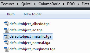
I then move the textures into "Textures-Final" folder and rename them:

Here are the textures:

Importing Albedo and Roughness into UE4
I reimport Normal and AO maps to make sure they are up to date.
I then import Albedo and Roughness maps. For Roughness texture, I disable "sRGB" through "Texture Editor:

I bring in Albedo and Roughness textures into "Material Editor" as "Texture Sample" nodes and connect them to proper inputs:

In perspective viewport:

Detail Albedo/Diffuse and Normal Map Texture
It would help to have additional texture detail for when the player gets very close to the Static Mesh.
I create two detail textures, one for Diffuse/Albedo and one for Normal. Diffuse/Albedo texture is desaturated and contains small detail. Normal texture detail is converted from Diffuse/Albedo detail:

Both textures are saved as "512x512" and saved as 24-bit targa.
I import both detail textures into UE4 and insert them in "Material Editor":

You have to convert each detail texture to a "Texture Object". Right-click on each detail texture sample node and choose "Convert to Texture Object":
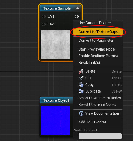
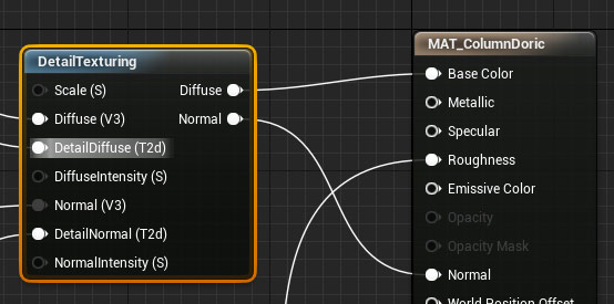
Insert "DetailTexturing" node:

Plug Albedo and Normal map into "Diffuse (V3)" and "Normal (V3)" inputs, then both detail textures into "DetailDiffuse (T2d)" and "DetailNormal (T2d)" inputs:

Finally, connect Diffuse and Normal outputs from "DetailTexturing" node into Material's input:
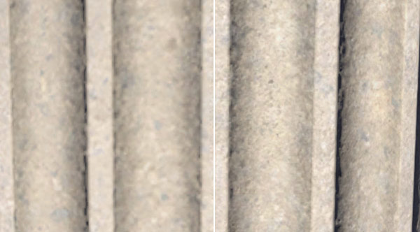
Here is the before/after comparison. You can see that after image (on the right) contains more detail and is sharper when viewed up close:
Creating Lightmaps
Lightmaps will help to display correct lighting/shadow information on your Static Meshes after baking/building lights. You have to create a second UV channel and unwrap it specifically for lightmaps. UE4 will then use this second UV channel to store and display proper lighting/shadow on your Static Mesh.
Back in Maya LT/Maya, I open up UV Editor and copy existing texture UVs into a new UV set by going to "UV Sets > Copy UVs to UV Set > Copy into New UV Set":

You can check and switch between different UV sets by going to "UV Sets" and choosing which UV set you want to work with:

- map1 is texturing set
- lightmap is the lightmap set (I renamed this UV set to "lightmap", by default it will be named "map2"
I make sure "lightmap" UV set is selected, then select all UVs and go to "Modify > Layout" options:

In "Layout UVs Options", under "Layout Settings" I set the following:
- Texture Map Size: 512
- Padding Units: Pixels
- Shell Padding: 4
- Tile Padding: 4

Click "Layout UVs".
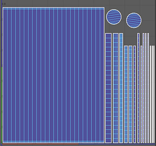
I re-export the mesh from Maya LT using the same FBX settings as before. I re-import the Static Mesh into UE4 and open "Static Mesh Editor":

In "Static Mesh Editor", enable "UV" and choose "UV Channel 1" to check if Lightmap channel was imported properly:

In "Details" panel of "Static Mesh Editor", scroll down to "Static Mesh Settings" and set "Light Map Coordinate Index" to "1". If you don't, UE4 will use default "UV channel: 0" for its lightmaps. I also set default "Light Map Resolution" to "512":

Click "Build" to build everything in the level, including lighting:

Static Mesh with lighting results:

Lightmaps look good enough. If the Static Mesh has light/shadow artifacts such as light/shadow patches where they shouldn't be then you'll need to re-UV the lightmap channel and reimport.
Creating Collision
The Static Mesh needs collision, otherwise the player, other objects and projectiles can go right through it.
If I create collision from "Static Mesh Editor", it won't be accurate enough. For example if I use "Collision > Add 26DOP Simplified Collision":

Here is the result:

I could try using "Auto Convex Collision" option, but this will create too many collision primitives. It's better to create custom collision from Maya LT/Maya.
Back in Maya LT/Maya I create 3 primitives using 12-sided cylinders. One for the middle, one for the bottom and one for the top:

I place all 3 collision primitives to overlap the low-poly mesh:
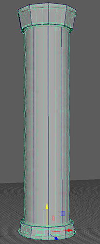
I make sure to include a small gap between each collision primitive so they don't touch each other. Nothing will happen if they do touch but it is recommended to leave a small gap between each primitive:

To make collision work from Maya LT inside UE4, you have to name collision primitives with the same name as the low-poly mesh but adding one of the following prefixes: UCX, UBX, USP or UCP.
Each is used for different collision primitive types. UCX being the most versatile collision prefix that offers advanced primitive modification.
Name of the low-poly mesh in Maya LT/Maya is:
- column_LP
Since I have 3 collision primitives, I will need to add sequential numbers to the end of the names.
Collision Primitive names are:
- UCX_column_LP_00
- UCX_column_LP_01
- UCX_column_LP_02

Using the "Outliner" I select all collision primitives and low-poly mesh:

Then export them together under the same name I've been using during all other exports, in my case it has been "column_doric". I use the same FBX options:

On reimport, UE4 will recognize the collision primitives and import them along with the Static Mesh. Checking in Static Mesh Editor:

You may also want to test it in-game by using "Play From Here" in perspective viewport.
Final Static Mesh
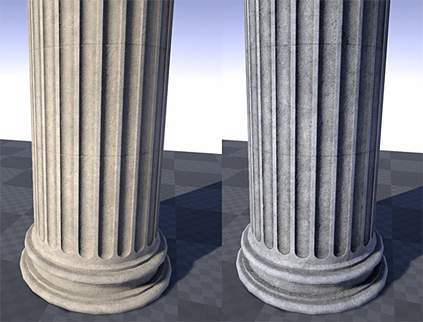
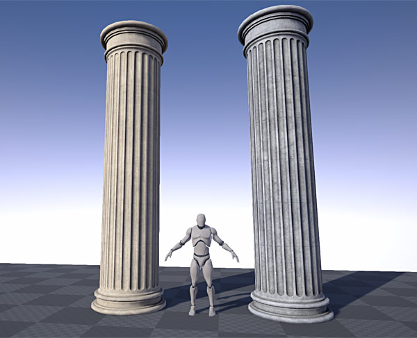
I created a different texture variation of the pillar in DDO and imported all the textures into Unreal Engine 4 using same steps from this tutorial.
Here are some final examples:

Step-by-Step Static Mesh Formula Tutorial Series
If this tutorial workflow was too fast and didn't give you enough of a step-by-step pipeline then you need "UE4 Custom Static Mesh Formula".
Home Terms of Use/Trademarks/Disclaimers Privacy Policy Donate About Contact
All content on this website is copyrighted ©2008-2024 World of Level Design LLC. All rights reserved.
Duplication and distribution is illegal and strictly prohibited.
World of Level Design LLC is an independent company. World of Level Design website, its tutorials and products are not endorsed, sponsored or approved by any mentioned companies on this website in any way. All content is based on my own personal experimentation, experience and opinion. World of Level Design™ and 11 Day Level Design™ are trademarks of AlexG.
Template powered by w3.css


 Maya Foundation: Home-Study Course - Model and UV Environments
 Substance 3D Painter Essentials - Master Texturing
 UE5: Fundamentals Vol.1 - Create with Unreal Engine 5
 UE5: Retro Office Project - Create Beautiful Interior Env
 UE5: Master Material Creation - Create Master Materials in UE5