World of Level Design™
Tutorials to Becoming the Best Level Designer and Game Environment Artist (since 2008)
UE5 Blueprint: Create Meshes Along a Spline Procedurally (Seamless and with Spacing)
Category: UE5
August 25, 2026
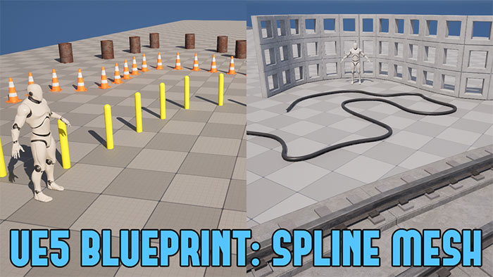
Modular Meshes or Blueprint Splines?
Both are useful and needed.
But there are times when modular meshes simply don't give you the flexibility to duplicate meshes how you would want.
Because repositioning modular meshes on the fly makes you adjust all other meshes you've already placed, adding significant extra work.
This is where Blueprint Splines come to the rescue.
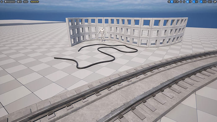
With Blueprint Splines you can duplicate any meshes along this spline then quickly adjust that spline and all the meshes on it.
This is perfect for environment assets that are seamless and continuous such as wires, cables, ropes, roads, walls.
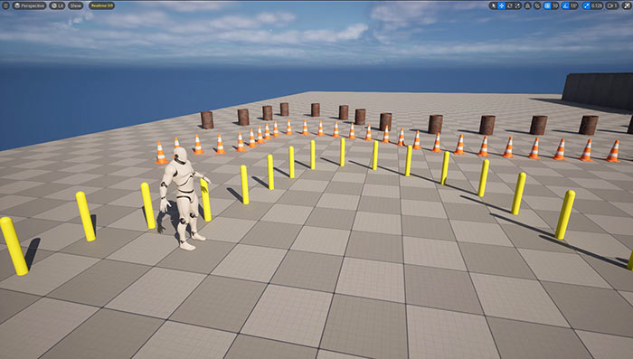
As well as for any meshes that require spacing between them such as fences, signs, electric poles or any props that needs distance between them.
And this is the tutorial that covers just that!
There are 2 Blueprint tutorials in this post:
- Part 1 covers generating seamless meshes along the spline. Perfect for cables, walls, ropes, and roads.
- Part 2 covers adding optional variation for controlled spacing when you need distance between individual meshes.
You will learn both Blueprint setup methods and how to create various variables to update the Static Meshes, Materials and Collisions to make your Blueprint highly reusable.
Don't Want to Create These Blueprints Yourself?
If you don't want to build these UE5 Blueprints yourself then the completed versions are available on the World of Level Design Patreon. Become WoLD Patreon supporter and grab these Blueprints and more.
- UE5 Blueprint Asset - Procedural Spline Mesh for Seamless Wires, Cables, Roads, Walls & More
- UE5 Blueprint Asset - Procedural Spline Mesh for Props That Needs Spacing/Distance (Fences, Poles, Signs & More)
Video Tutorial 1/2: Seamless Spline Meshes for Wires, Cables, Walls Roads & More
This first tutorial shows how to build a reusable Blueprint that generates continuous, seamless meshes along a spline. It's perfect for wires, cables, roads, walls or any mesh that must follow a path and connect meshes flush end-to-end.
Important Mesh Creation Considerations
Start with a Static Mesh that will be your default. I'll be using a simple cylinder that will work great for cables or wires. But use any mesh you want as the default.
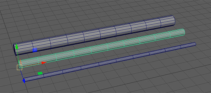
Keep these points in mind:
- Note the mesh width. In this example the cable is 150 units (cm) long. Knowing this size makes troubleshooting easier.
- Add enough edge segments. Extra loops allow the mesh to bend smoothly along the spline without breaking.
- Place the pivot at one end of the mesh (the start or end point) and orient the mesh along the X-axis. UE5 defaults to X as the forward axis direction, this orientation simplifies initial setup. But we'll create a variable to change the axis orientation if needed.
- Unwrap the UVs on the mesh.
Imported Mesh Overview in UE5
Few things you should know what I did to the default Static Mesh I'll be using so we are on the same page:
- I've imported the mesh into UE5 and assigned a simple default Material.
- I generated collisions on import but you could create custom collisions to import along with your mesh if needed.
Creating the Blueprint Actor
Right-click in the Content Browser and choose Blueprint Class and choose Actor:
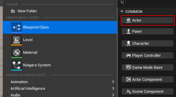
Name it something clear such as BP_SplineMesh_Cable and double click on this Blueprint to open Blueprint Editor.
Adding the Spline Component
In the Components panel, click Add and search for Spline (not Spline Mesh):
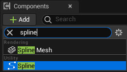
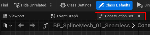
All remaining work happens in the Construction Script:
Calculating Mesh Size with Get Bounding Box
This will automatically calculate the size of the mesh.
Create a new variable and name it:

Set the variable type to Static Mesh > Object Reference:
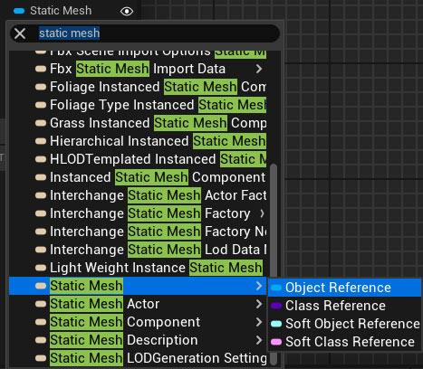
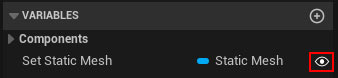
Make it public (click the eye icon):
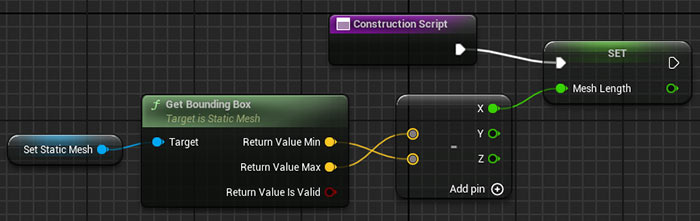
Follow the steps to set up Get Bounding Box for calculating the size of the Static Mesh:
- Drag Set Static Mesh variable into the Construction Script and choose Get.
- From its output, search for Get Bounding Box.
- Right-click the Return Value and Split Struct Pin.
- Subtract Maximum from Minimum (drag from Maximum, search for Subtract, connect Minimum to the bottom pin).
- Split the Subtract output, then drag from the X pin and choose Promote to Variable.
- Name the new float variable Mesh Length (don't need to make this public).
- Connect Construction Script execution pin into the Set node for Mesh Length.
Getting the Spline Length
This will automatically calculate the size of the spline so it can begin to insert Static Meshes into this spline based on the mesh size.
- Drag the Spline component you added at the start into the Construction Script.
- From it, search for Get Spline Length.
- Divide the spline length by Mesh Length.
- Truncate the result (removes decimals).
- Subtract 1 from the truncated value. This prevents a new mesh segment from appearing until the full mesh length is reached.

Setting Up the For Loop
- Right-click and add For Loop.
- Connect the Subtract node's output to the Loop's Last Index.
- Connect the Set Mesh Length into For Loop.
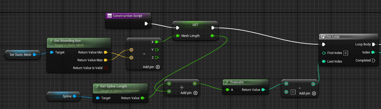
click on image to view full size
Set Static Mesh
This will allow you to change to any Static Mesh you want to use.
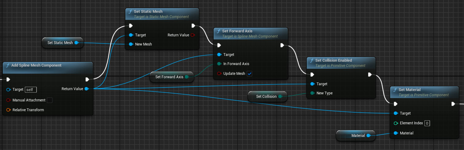
From the Loop Body: Add a Spline Mesh Component.
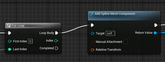
- From its execution pin, add Set Static Mesh.
- Connect the Set Static Mesh variable to the New Mesh pin.
- Connect Add Spline Mesh Component's Return Value to the Target.
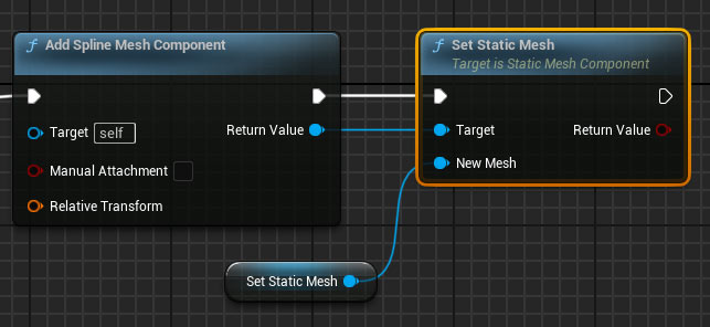
- Compile then set a default mesh in the variable's details (your cable mesh).
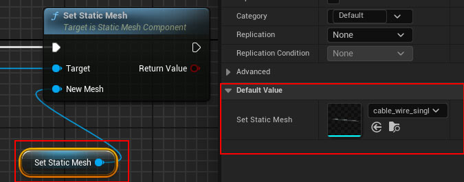
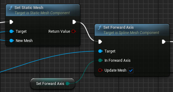
Set Forward Axis
This will allow you to change forward axis to a Static Mesh if it wasn't created on x-axis.
- Add Set Forward Axis.
- Connect the Return Value from Add Spline Component to Set Forward Axis Target.
- Right-click the Forward Axis pin and Promote to Variable. Keep the default as X. Make the variable public.
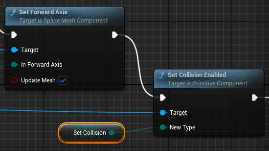
Set Collision Enabled
This will allow you to have Static Mesh collisions that are positioned along the spline.
- Add Set Collision Enabled.
- Connect the Return Value from Add Spline Component to Set Collision Enabled Target.
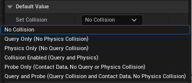
- Promote the New Type pin to a public variable named Set Collision.
- Default it to No Collision or to Collision Enabled (Query and Physics)
Set Material
This will allow you to change to any new Material or Material Instance on the Static Mesh.
- Add Set Material.
- Connect the Return Value from Add Spline Component to Set Material Target.
- Promote the Material pin to a public variable named Material.
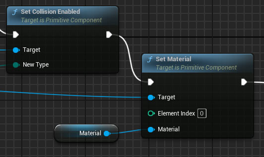
Note: make sure Set Material is Target is Primitive Component (disable Context Sensitive in the search if needed to find the correct node):
Here is the entire Static Mesh setup:
click on image to view full size
Setting Start and End Positions
- From the Set Material execution pin or whatever the last Set you have from previous setup, add Set Start and End (Target is Spline Mesh type, disable Context Sensitive during search if necessary).
- Connect the Add Spline Mesh Component Return Value to Set Start and End Target.
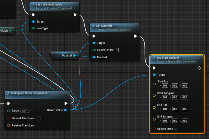
You now need location and tangent information from the Static Mesh.
- Add Get Location at Distance Along Spline and Get Tangent at Distance Along Spline.
- Insert Mesh Length variable into the graph.
- Multiply For Loop's Index by Mesh Length. Feed the result into the Distance pin of Get Location and Get Tangent nodes. These provide the start position and start tangent.
- Insert Spline component into the graph and connect it into Target inputs for Get Location and Get Tangent nodes.
- Duplicate Get Location and Get Tangent setup.
- Add 1 from For Loop Index output before multiplying by Mesh Length. This will give you the end position and end tangent of the Static Mesh.
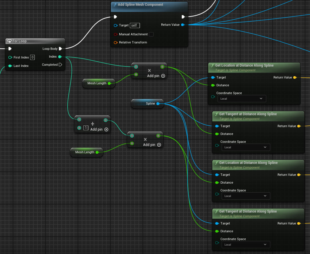
click on image to view full size
Add Clamps to Tangents
You have to clamp Start and End Tangents, otherwise you'll have Static Mesh distortions as you increase the Spline length.
- From each Get Tangent Return Value, add Clamp Vector Size.
- Connect Mesh Length to the Max pin of both Clamp nodes.
- Feed the clamped results into Start Tangent and End Tangents.
- Connect Get Location Return Values to Start and End Pos.
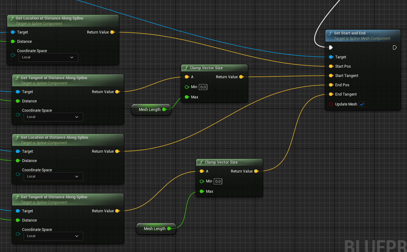
click on image to view full size
Complete UE5 Blueprint Setup for Seamless Meshes
This is the complete UE5 Blueprint Spline Mesh setup for seamless meshes along the spline:
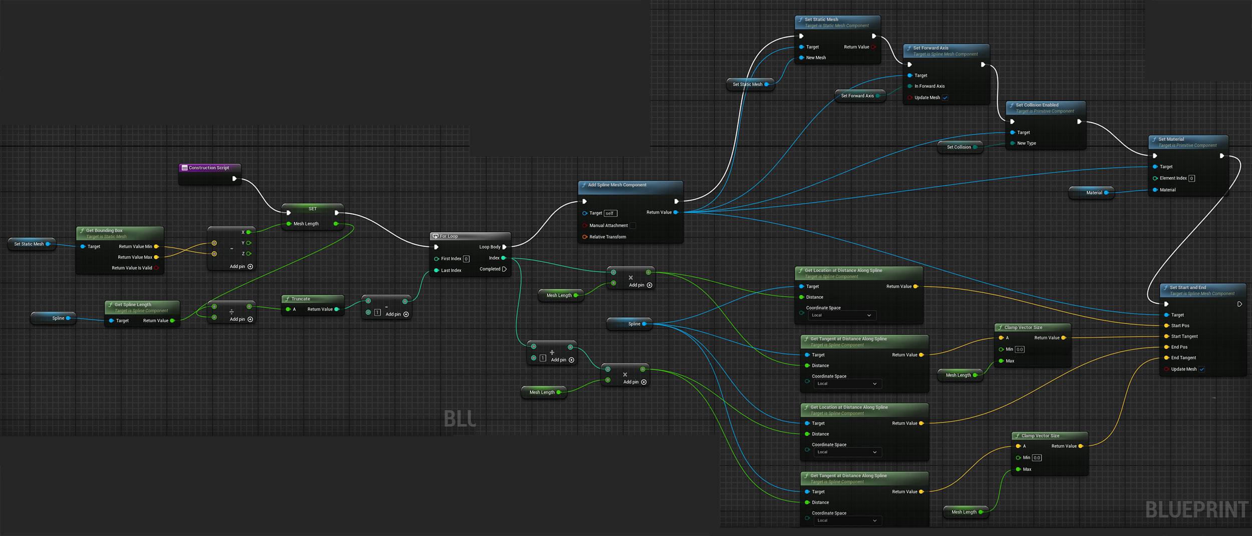
click on image to view full size
Compile and Test
Compile and save the Blueprint.
Drag the Blueprint Actor into your level and test.
- Hold Alt while dragging a spline point to add new control points and curve the path.
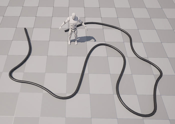
Use the exposed variables in the Blueprint to:
- Swap to any new Static Mesh.
- Change Forward Axis if the mesh was authored on Y or Z.
- Enable or disable collisions.
- Override the default Material or Material Instance.
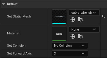
Optional Tips
Removing the Subtract 1 after Truncate makes new segments appear as soon as the spline length increases.
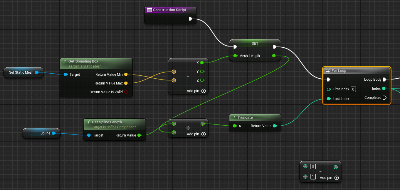
click on image to view full size
This may work for cables and wires but will show noticeable distortion on larger meshes for walls, roads and more.
Video Tutorial 2/2: Spacing Between Meshes Along a Spline for Fences. Signs, Props & More
This second tutorial shows how to create a reusable Blueprint that generates Static Meshes along a spline but adds optional spacing or distance between them. It will work great for fences, light poles, electric poles, signs or other props that needs space separation between meshes.
Adding Spacing
We going to take the previous setup and modify 2 sections.
- Section 1: before For Loop
- Section 2: right after for Loop
Adding Spacing Before For Loop
Here is the new setup to add Spacing.
- Create a new Float Variable and call it Spacing.
Set it up like so with the previous network:
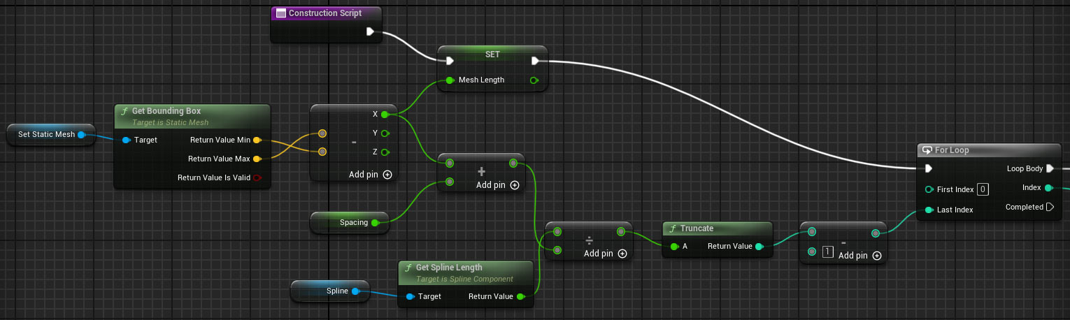
click on image to view full size
Adding Spacing After For Loop
Here is the new math setup for making Spacing work. This is done out of Index of For Loop:
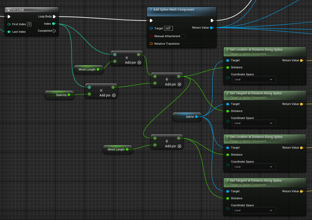
click on image to view full size
Complete UE5 Blueprint Setup for Seamless and with Spacing
This is the complete UE5 Blueprint Spline Mesh setup for seamless meshes along the spline:
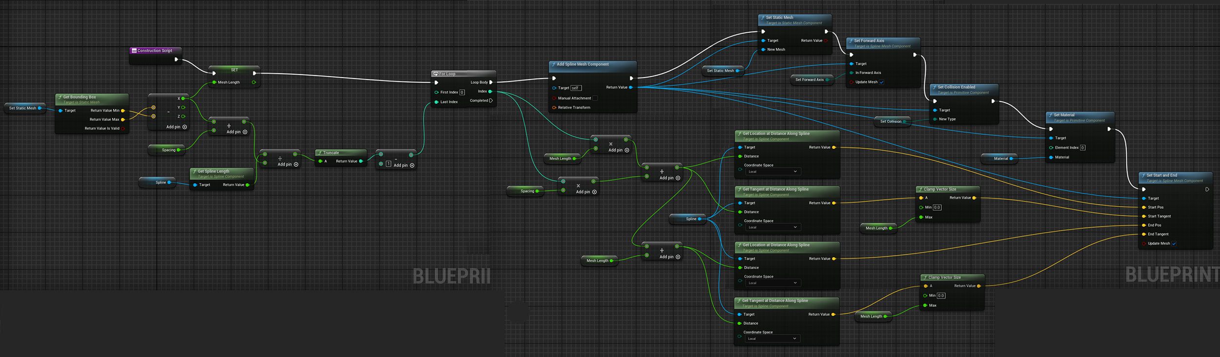
click on image to view full size
In Closing
You now have a reusable Blueprint for placing meshes along a spline, procedurally.

SUBSCRIBE & GET FREE UE5 PDF GUIDE
Subscribe to receive NEW/UPDATED and FREE "UE5 Beginner's Quick Start Guide" PDF (90 pages).

Visit this page for more info about the guide...
TOP 7 TUTORIAL COURSES FOR 2026
 Modular Environment Design Masterclass
 Maya Foundation: Home-Study Course
 Substance 3D Painter Essentials
 UE5: Fundamentals Vol.1
 UE5: Retro Office Project
 UE5: Master Material Creation
 Preproduction Blueprint
TUTORIAL CATEGORIES
UE5 FUNDAMENTALS VOL.1 COURSE
UE5: RETRO OFFICE PROJECT

MODULAR ENVIRONMENTS MASTERCLASS
LEARN THE PREPRODUCTION PROCESS

ABOUT WoLD & ALEXG

My name is AlexG. I am self-taught level designer, game environment artist and the creator of World of Level Design.com. I've learned everything I know from personal experimentation and decades of being around various online communities of fellow environment artist and level designers. On World of Level Design you will find tutorials to make you become the best level designer and game environment artist.
Home Terms of Use/Trademarks/Disclaimers Privacy Policy Donate About Contact
All content on this website is copyrighted ©2008-2024 World of Level Design LLC. All rights reserved.
Duplication and distribution is illegal and strictly prohibited.
World of Level Design LLC is an independent company. World of Level Design website, its tutorials and products are not endorsed, sponsored or approved by any mentioned companies on this website in any way. All content is based on my own personal experimentation, experience and opinion. World of Level Design™ and 11 Day Level Design™ are trademarks of AlexG.
Template powered by w3.css